Federal Agency for Education educational institution higher professional education "TOMSK POLYTECHNICAL UNIVERSITY" Surzhikov "_____" ________________2006 MEASURING THE MAGNETIC FIELD STRENGTH OF INDUSTRIAL FREQUENCY GENERATED BY HIGH VOLTAGE INSTALLATIONS Guidelines to the laboratory work No. 2 on the course "Electromagnetic compatibility in the electric power industry" for students of the specialty "Power Engineering" Tomsk 2006 Department of ESWT ELTI TPU 2 allowable norms tension magnetic field industrial frequency for personnel and the public, familiarize themselves with the use of the PZ-5 power frequency field strength meter. Measure the strength of the magnetic field created by the current of the laboratory setup. General information Electrical installations of electric power and industrial enterprises, research laboratories are a source of a magnetic field (MF) with a frequency of 50 Hz. The magnetic field is one of the components electromagnetic field, which is created by the current flowing through the conductor. The magnetic field takes place in electrical installations of all voltage classes. Its intensity is higher near the terminals of generators, current conductors, block power transformers and autotransformers for communication of outdoor switchgear of different voltages (especially at the level of the tank connector), as well as indoor switchgear 6-10 kV and near them. In rooms near switchgear, near current conductors, near electric motors, switchgear, cable and overhead lines At all voltages, the intensity of the magnetic field is significantly lower. More a difficult situation with the system cable lines building. When a leakage current appears in the cable line, the resulting imbalance, i.e. the inequality of zero of the total current along the cable line creates a magnetic field in the surrounding space that slowly decreases with increasing distance from the cable in question. In addition, the presence of leakage currents in the power supply system of the building leads to the flow of currents through the metal structures and piping systems, which also causes an increase in the levels of IF MF. In Figure 1.1. data are given on sources that create a magnetic field of industrial frequency in industrial premises, and in Fig.1.2. approximate values of magnetic field strengths from these sources. Rice. 1.1. Distribution of sources by types of the total number of surveyed premises Fig. 1.2. Ranges of MF IF values at workplaces from external sources by types Department of ESWT ELTI TPU 3 The impact of a magnetic field on personnel can be both general and predominantly local (on the limbs). An alternating magnetic field induces eddy currents in the human body According to modern ideas the induction of eddy currents is the main mechanism of the biological action of magnetic fields. The main parameter characterizing it is the eddy current density. The permissible value of the eddy current density in the body is the basis of these SanPiN and all the hygienic regulations of the magnetic field in force in the world (with different hygienic safety factors). The intensity of the impact of the magnetic field is determined by the intensity (N), or magnetic induction (V) (their effective values). The magnetic field strength is expressed in A/m (a multiple of kA/m), the magnetic induction is expressed in Tesla (T, fractional values mTl μTl nT). The induction and intensity of the magnetic field in air are related by the following relation: B = μ 0 H = 4π ⋅ 10 −7 ⋅ H T where μ 0 = 4π ⋅ 10 −7 H/m is the magnetic constant, H is the magnetic field strength A/m. The maximum allowable levels (MPL) of the magnetic field are set depending on the time spent by personnel for the conditions of general (on the whole body) and local (on the limbs) impact (Table 1.1.) Maximum allowable levels of the magnetic field (SanPiN 2.2.4.1191-03) Table 1.1. Stay time (h) Permissible levels MP H(A/m)/V(µT) under the influence of General Local<1 1600/2000 6400/8000 2 800/1000 3200/4000 4 400/500 1600/2000 8 80/100 800/1000 В 2001 г. Всемирная организация здравоохранения (ВОЗ) в информационном сообщении “Electromagnetic fields and public health. Extremely low frequency fields and cancer” признала, что в свете современных научных представлений магнитное поле промышленной частоты (МП ПЧ) со значениями плотности магнитного потока превышающими 0,3 – 0,4 мкТл в условиях продолжительного воздействия возможно является канцерогенным фактором окружающей среды. Поэтому ВОЗ рекомендует придерживаться предупредительного принципа, т е всеми доступными средствами ограничивать воздействие МП ПЧ на организм человека. Биологическая эффективность МП зависит от интенсивности и продолжительности воздействия. Показана возможность неблагоприятного влияния МП на здоровье человека. Реакции организма имеют неспецифический характер. Обследование взрослого населения показало, что существует еще одна проблема лежащая в аспекте появления отдаленных последствий у лиц, имеющих контакт с МП ПЧ и поднятая во многих публикациях, заключается в возможности развития нейродегеративных болезней и нейрологических расстройств. К этой возможной патологии в настоящее время относят депрессивный синдром, прогрессирующую мышечную атрофию (боковой амитрофический склероз), болезни Альцгеймера и Паркинсона, а также возможное учащение случаев самоубийств. Согласно докладу рабочей группы CIGRE для всех людей допускается неограниченное время воздействия МП напряженностью 80 А/м. Однако, в последние годы все чаще говорят о необходимости снижения допустимого уровня МП, зачастую локально, например, около школ, площадок для игр и т.д. В свою очередь, причиной повышенного уровня магнитного поля, как правило, являются недостатки в проектировании, монтаже и эксплуатации распределительных сетей в зданиях. Российская предельно-допустимая гигиеническая норма 10 мкТл внутри жилых помещений и 50 мкТл на территории зоны жилой застройки (СанПиН 2.1.2.1002-00). Всемирная организация здравоохранения (ВОЗ) рекомендует придерживаться в качестве безопасного уровня 0,2 мкТл, учитывая относительную неизученность отдаленных последствий воздействия этого фактора. Магнитные поля промышленной частоты биологически значимого уровня 0,2 мкТл и выше и продолжительного периода воздействия имеют широкое распространение в условиях непрофессионального воздействия. Они фиксируются на постоянных рабочих местах не зависимо от профессиональной категории работающих, а также внутри жилых помещений (табл. 1.2.). Кафедра ЭСВТ ЭЛТИ ТПУ 4 Уровни магнитного поля промышленной частоты бытовых электроприборов на расстоянии 0,3 м Бытовой электроприбор От, мкТл До, мкТл Пылесос 0,2 2,2 Дрель 2,2 5,4 Утюг 0,0 0,4 Миксер 0,5 2,2 Телевизор 0,0 2,0 Люминесцентная лампа 0,5 2,5 Кофеварка 0,0 0,2 Стиральная машина 0,0 0,3 Микроволновая печь 4,0 12,0 Электрическая плита 0,4 4,5 Меры защиты персонала и населения от воздействия магнитного поля Измерение напряженности (индукции) МП должно производиться на всех рабочих местах эксплуатационного персонала электроустановок, в местах прохода персонала (в т.ч. вблизи экранированных токопроводов, под шинными мостами и т.п.), а также в производственных помещениях с постоянным пребыванием персонала расположенных на расстоянии менее 20 м от токоведущих частей электроустановок, в т.ч. отделенных от них стеной. Обеспечение защиты работающих от неблагоприятного влияния МП осуществляется путем проведения организационных и технических мероприятий. К организационным относятся мероприятия, обеспечивающие соблюдение требований ограничения продолжительности пребывания персонала в воздействия МП (без нарушения сложившейся системы эксплуатационного обслуживания электрооборудования) и организации рабочих мест на расстояниях от токоведущих частей оборудования, обеспечивающих соблюдение ПДУ. При проектировании электроустановок организационные мероприятия включают - отказ от размещения производственных помещений, рассчитанных на постоянное пребывание персонала вблизи токоведущих частей электроустановок, а также под и над токоведущими частями оборудования (например, токопроводами), за исключением случаев, когда уровни МП по результатам расчета не превышают предельно допустимые. - расположение путей передвижения обслуживающего персонала на расстояниях от экранированных токопроводов и (или) шинных мостов, обеспечивающих соблюдение ПДУ. - исключение расположения токоограничивающих реакторов и выключателей в соседних ячейках РУ 6-10 кв. - при проектировании ВЛ предпочтение должно отдаваться двухцепным ВЛ с расположением фазных проводов, обеспечивающим максимальную компенсацию МП от фазных проводов обеих цепей. -при проектировании КЛ их расположение должно обеспечивать соблюдение допустимых значений МП v поверхности земли При эксплуатации электроустановок организационные мероприятия включают следующее: - зоны с уровнями МП превышающими предельно допустимые, где по условиям эксплуатации не требуется даже кратковременное пребывание персонала (например, камеры выводов турбогенераторов), должны ограждаться и обозначаться соответствующими предупредительными знаками; - осмотр электрооборудования находящегося под напряжением должен осуществляться из зон с уровнями МП удовлетворяющими нормативным требованиям; ремонт электрооборудования следует производить вне зоны влияния МП. К техническим относятся мероприятия, снижающие уровни МП на рабочих местах путем экранирования источников МП или рабочих мест. Экранирование должно осуществляться посредством материалов с высокой относительной магнитной постоянной или активных экранов. Аппаратура для измерения Для измерения напряженности магнитного поля используется измеритель напряженности поля промышленной частоты типа П3-50. Измеритель напряженности поля промышленной частоты ПЗ-50 предназначен для измерения среднеквадратичного значения напряженности магнитного поля промышленной частоты возбуждаемого вблизи электроустановок высокого напряжения в диапазоне от 0,1 до 1800 А/м. Кафедра ЭСВТ ЭЛТИ ТПУ 5 Измеритель состоит из антенны-преобразователя (АП) НЗ-50 и устройства отсчетного УОЗ – 50. АП типа НЗ-50 представляет собой экранированную рамочную антенну электрически малых размеров (средний диаметр рамки 80 мм, число витков 5600). При помещении АП в МП в обмотке антенны наводится переменное напряжение пропорциональное проекции вектора напряженности поля на ось перпендикулярную плоскости рамки. Переменное напряжение далее через кабель поступает на устройство отсчетное УОЗ-50, преобразующее аналоговый сигнал, поступающий с АП в цифровой сигнал и обеспечивающее индикацию напряженности МП в абсолютных единицах А/м. В зависимости от положения переключателей при измерении напряженности МП могут быть установлены пределы измерения указанные в табл. 1.3. Таблица 1.3. Положение Предел измерения переключателя Положение А/м х0,1/х1/х10 переключателя 2/20/200 2000 х10 200 200 xl 200 20 х1 20 2 хl 2 0,2 х0,1 2 Для определения среднеквадратического значения модуля вектора напряженности МП следует измерить в выбранной точке пространства проекции вектора напряженности поля на три взаимно ортогональные оси НХ, НY, HZ. После чего определить модуль вектора напряженности electric field H according to the formula: H \u003d H X + NU + H Z 2 2 2 Circuit for measuring the magnetic field The circuit that provides the creation of a magnetic field is assembled in a laboratory installation by turning on the corresponding magnetic starters and is shown in Fig. 1.1. 1 S1 AT1 S2 T1 R1 0 ~ 220V V 2 R2 0 A 1 2 1.3. Scheme for creating an electric field of industrial frequency Operation procedure 1. Before starting work, get acquainted with the device of the PZ-50 field strength meter, the measurement procedure; Department of ESWT ELTI TPU 6 2. Make sure that all switches on the main panel of the laboratory unit are in the neutral position (“0” position). The handle of the autotransformer must be in the extreme position when rotated counterclockwise; 3. With the laboratory installation turned off, measure the projections of the magnetic field strength vector (the so-called background values) at a point in space specified by the teacher. Record the measurement results in table. 1.4. 4. By switching the key S1 from position "0" to position "1" turn on the laboratory unit; 5. By transferring the key S 2 from position "0" to position "2", apply voltage to the autotransformer; 6. Set the current in the conductor using an autotransformer I 1 \u003d 0.2 A. 7. Measure the rms value of the modulus of the magnetic field vector. To do this, at a point in space specified by the teacher, the projections of the magnetic field strength vector are measured. Record the measurement results in table. 1.4.. 8. Repeat the measurements by changing the current values in the conductor through 0.2A within the adjustment range of the autotransformer. Record the measurement results in table. 1.4.. 9. Construct the dependence of the electric field strength module depending on the magnitude of the current in the conductor. 10. Compare measured field strength levels with background values. 11. Give an explanation of the results obtained. 12. Answer security questions. Table 1.4. Current value in HX NY HZ N Note conductor, A A/m A/m A/m A/m 0.0 Unit disabled 0.2 Unit enabled 0.4 0.6 …. Repeat steps 1-10 for several points in space specified by the teacher. The content of the report The report must contain the following mandatory components: 1. Title page, drawn up in accordance with the established requirements; 2. Purposes of performance of work; 3. A summary of theoretical issues regarding the content of the work; 4. Terms and definitions; 5. Used technical means; 6. Description of the task (setting tasks to be performed in the LR process) 7. Description of the main part (brief description of the laboratory facility, its scheme, measurement results presented in the form of tables and graphs); 8. Analysis of the obtained results; 9. The report is compiled in general for a team of students. 10. Formatting the text of the LR report is carried out in accordance with the requirements of STO TPU 2.5.01-2006 Test questions 1. What is the reason for the appearance of a magnetic field from high-voltage devices? 2. What measures are taken to reduce the magnetic field strength at power plants and substations? 3. List the factors that affect the magnitude of the magnetic field strength from high-voltage devices. 4. Why does the presence of vegetation under overhead lines reduce the electric field strength? Department of ESWT ELTI TPU 7 Department of ESWT ELTI TPU
Before considering the measurement of magnetic field strength, it is necessary to understand the basic concepts of magnets and the magnetic properties of various substances.
There are different types of magnets. Constants are obtained from solid materials. They have natural properties and do not depend on any external influences of currents. Electromagnets are artificial in nature, their basis is a core made of metal having magnetic properties. It is they who create magnetic fields under the influence of an electric current passing through the winding, inside which the core is located.
Having the shape of a rod, they are most clearly manifested at its ends. When hanging it by the middle in a free position on a horizontal plane, it will occupy a position in which the approximate direction from north to south will be observed. The ends of the rod also have the corresponding names for the north and south poles. In two identical magnets, the poles with different names are attracted to each other, while the poles of the same name, on the contrary, repel.
If you bring ordinary, non-magnetized iron to a magnet, it acquires magnetic properties for a certain time with the formation of poles. Some materials, such as steel, can acquire weak permanent magnet properties.
The attraction of metal objects at a distance is explained by the presence in space near any magnet of certain field values. The ends of the magnets have the greatest 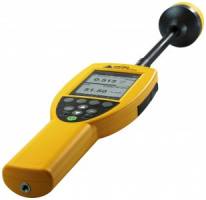 the intensity of the magnetic field.
There is another quantity that explains the magnetic effects of electric currents. For example, electricity passed through the coil wire with a long length. Inside this coil is a material that can be magnetized. The magnetizing force depends on the value of the force in the coil and the number of its turns. Thus, the field strength is equal to the amount of magnetizing force that falls on a certain segment of the coil.
The measurement of the magnetic field strength is carried out in the unit "ampere / meter", with its help the degree of magnetization of the material placed inside the coil is determined.
The physical measurement of this quantity is made by a special device - a meter of magnetic and electric fields. This device allows you to obtain the necessary results with high accuracy and covers a very wide range of radiation of various frequencies.
In precision studies, it is necessary to know exactly the magnetic field strength, which is created using the various coils and electromagnets described above. In most cases, the magnetic field strength is determined experimentally. This section discusses the main methods for measuring the magnetic field strength: ballistic, magnetic probes, NMR method, electrodynamic, magnetic potential meters, magnetic field meter and a method based on the Hall effect.
When measuring the magnetic field strength by the ballistic method, a small coil is used, the frame of which is made of insulating material. Several turns of copper wire with a diameter of 0.05-0.8 mm are wound on this frame, which are connected to a ballistic galvanometer and the secondary winding of a reference coil. The dimensions of the measuring coil depend on the volume of space where it is required to determine the magnitude of the magnetic field strength. If the measuring coil is placed in such a way that the magnetic field strength vector is directed perpendicular to the plane of the turns, then when the coil is quickly removed from the magnetic field, e.g. d.s.
where the number of turns of the coil is the change in the flux of magnetic induction through the area of the turns of the coil.
Since where is the change in the magnetic induction in the gap, it follows from (3.1) that
![]()
where is the total resistance of the ballistic circuit, the amount of electricity that flows through the galvanometer.
From the theory of a ballistic galvanometer, it is known that the deviation of the movable frame of the galvanometer is proportional to the amount of electricity that has passed through the galvanometer, that is, where is the ballistic constant of the galvanometer.
Integrating (3.2), we obtain
![]()
Since the value is measured only modulo, the minus sign can be omitted.
Due to the fact that the resistance of the measuring circuit, consisting of the resistance of the galvanometer and the resistance of the external circuit, remains constant during the measurement process, we denote the product in formula (3.3) through which is called the setting constant. The constant characterizes the sensitivity of the installation in relation to the magnetic flux.
When measuring the magnetic field strength by the ballistic method, two cases should be considered: 1) the coil is quickly removed from the magnetic field; in this case, the magnetic induction changes from a certain value B to zero; 2) the measuring coil is rotated by 180° using a special device, while the magnetic induction changes from to . In addition to these two methods, the field can be measured when the current is turned on and off in the magnetizing circuit. In the first case, it follows from (3.3):
![]()
In the second case, the formula for the calculation will differ from (3.4) only in that the denominator will have a coefficient of 2.
Thus, to determine the magnetic field strength by the ballistic method, it is necessary to know the number of turns of the measuring coil, the cross-sectional area of this coil, the installation constant and the rejection of the galvanometer frame. To calculate the magnetic field strength using formula (3.4), you must first determine the value of what is done using a reference coil, which in its simplest form is a long solenoid, in the middle part of which the secondary winding is wound,
or an inductor connected in series with a ballistic galvanometer and a measuring coil.
The magnetic field inside the reference coil is calculated by the formula
![]()
where the number of turns of the primary winding, I is the length of the solenoid, the strength of the current passed through the primary winding
The magnetic flux through the turns of the secondary winding will be equal to
![]()
where is the area of the reference coil, the number of turns of the secondary winding.
From (3.5) and (3.6), according to formula (3.4), we obtain
![]()
After the definition, it is easy to calculate the magnetic field strength using formula (3.4). It should be remembered that during the measurement process it is necessary to keep the resistance of the measuring circuit constant, since only in this case the constant will not change. This condition is easy to fulfill if, during the measurement process, the ballistic galvanometer is connected in series with the secondary winding of the reference and measuring coils.
Federal Agency for Education
State educational institution of higher professional education
Nizhny Novgorod State Technical University
Vyksa branch
Department of O&OPD
The magnetic field of the solenoid.
Hall Sensor
Lab #2-6
Compiled by: V.P. Maslov, I.I. Rozhkov, O.D. Chestnova, R.V. Shcherbakov.
A method for determining the induction of the magnetic field of a solenoid based on the Biot-Savart-Laplace law and using a Hall sensor is given.
Scientific editor A.A. radionov
Goal of the work: get acquainted with the definition of the magnetic field induction of a solenoid based on the Biot-Savart-Laplace law and using a Hall sensor.
THEORETICAL PART
In the space surrounding conductors with current, moving charges, magnets, a magnetic field arises, which can be detected by its effect on another conductor with current or a magnetic needle. The magnetic field at each point in space can be quantitatively described using the magnetic field strength vector or using the magnetic field induction vector  . In vacuum vectors And
  related by the ratio:
 , (1)
, (1)
where μ 0 = 4π·10 -7 H/m is the magnetic constant.
Units And A/m
and TL, respectively. In a medium with magnetic permeability μ

To calculate the strength and induction of the magnetic field, use the Biot-Savart-Laplace law, according to which the elementary strength of the magnetic field  , created by a conductor element with current
  at some point in space at a distance
  , is determined by the expression
 , (2)
, (2)
Where  - unit vector along .
Vector modulus
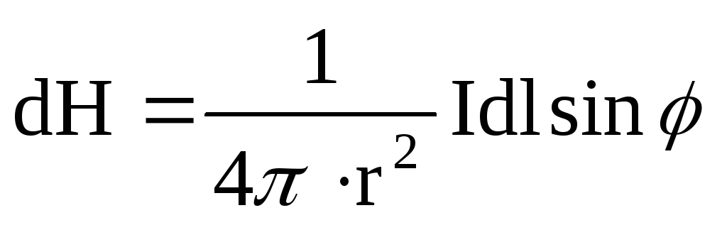 ,
,
where φ is the angle between the vectors  And
And  .
.
To find the resulting strength created by a conductor of finite dimensions, it is necessary to use the principle of superposition of magnetic fields and find the vector sum of elementary strengths  from all elements conductor. We apply formula (2) to calculate the magnetic field strength on the axis of a circular coil with current (Fig. 1).
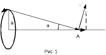
On fig. 1 component dH 1 created by the current element , according to (2) is defined as
 ,
,
where it is taken into account that the angle between And straight. From the symmetry of the elements turn with respect to point A, it can be seen that the resulting magnetic field strength is directed along the axis so that  , that is
 .
.
On the right side of the last formula, all-quantities except dl are constant (for a given point A), so integrating no dl gives
 ,
,
or according to fig. 1
 (3)
(3)
the value  can be found by formula (1).
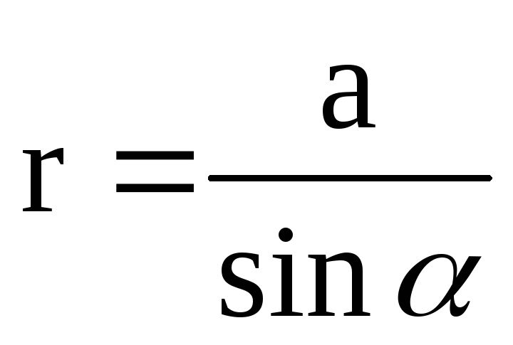
Let there be turns per unit length of the solenoid (Fig. 2), then section d z contains ndz turns, which, according to (3), at point A on the axis will create tension
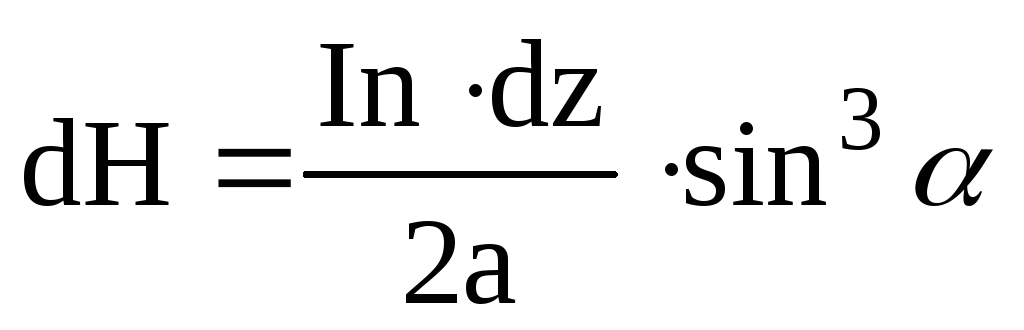 . (4)
. (4)
On fig. 2 L is the length of the solenoid, a is the radius of the turns of the winding, 0 is the central point on the axis of the solenoid. ОА=z - point A coordinate.
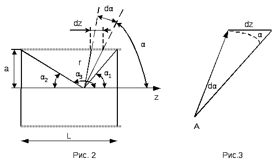
On fig. 3 elements are shown separately dz, radius vector  and angles α and dα. From the geometric constructions of Figures 2 and 3 it follows:
 ;
;
 ;
;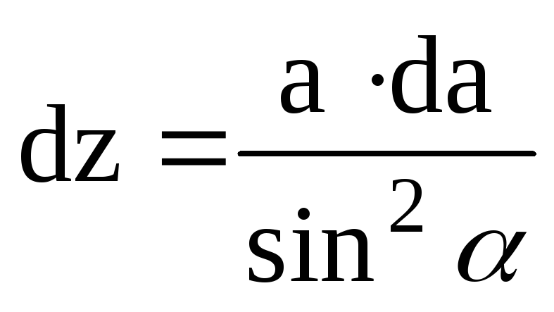 .
.
We substitute these relations into (4) and integrate over α within the range from α 1 to α 3:
 .
.
Given that  , we get
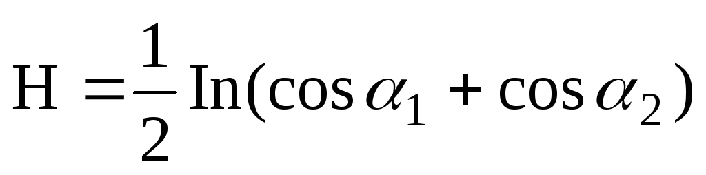 (5)
(5)
In the case of an infinitely long solenoid (l>>α) at the central point 0 α 1 →0, α 2 →0,
 . (6)
. (6)
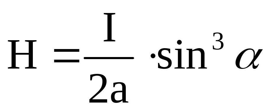
It also follows from (5) that when moving from the center to the edge of the semi-infinite solenoid (at the edge z=0.5L, α 1 =π/2, α 2 → 0), the intensity is halved:
 . (7)
. (7)
We obtain the induction of the magnetic field by adding formula (1) to expressions (5), (b), (7). Note that the derivation of formula (6) for an infinitely long solenoid turns out to be much simpler on the basis of the total current law.
Any S.I.
Subject:"Magnetism".
Purpose of the lecture: To give students the basic concepts and definitions used in the electromagnetism section: magnetic field, intensity, dia-, para- and ferromagnets, magnetic induction. Give basic laws and definitions.
Lecture plan
Magnetic phenomena have been known since ancient times. At the same time, the magnetic properties of the Earth were noticed, due to which the bar magnet, balanced on the tip of the needle, was installed almost along the geographic meridian. (Such a compass existed in China about 3,000 years ago.)
In the 18th century, attention was paid to the magnetization of iron objects and the remagnetization of the compass near a lightning discharge.
This suggested the connection between magnetic phenomena and electrical ones. This was confirmed by the Danish physicist H. K. Erstred. He found that an electric current acts on a nearby magnetic needle, orienting it perpendicular to the wire. At the same time, the French physicist Ampere experimentally discovered the magnetic interaction of two conductors with current.
Consequently, another type of field arises around moving electric charges (currents) - a magnetic field, through which these charges interact with magnetic or other moving electric charges.
Since the magnetic field is a force field, it can be represented by lines of force, for example:
Bar magnet magnetic field
The magnetic field created by the current I in a rectilinear conductor (Erstrede's experiment). Field lines are concentric circles, perpendicular to a wire, whose centers are on that wire.
Direction of field lines magnetic field is determined gimlet rule: the handle of a gimlet screwed in the direction of the current rotates in the direction of the magnetic lines of force.
Unlike the lines of force of the electric field, magnetic lines of force are always closed.
Take a conductor of arbitrary shape, through which the current flows I.
We divide the conductor into a set of elementary sections and consider one of them dl. It creates a magnetic field in space. Exactly ABOUT this field, located at a distance r from dl, place the current element I 0 dl 0 . Then, according to Ampère's law, a force will act on this element
where α is the angle between the current direction I Location on dl and the direction of the radius vector r;
β is the angle between the direction of the current element I 0 dl 0 and normal n to the plane Q containing dl And r.
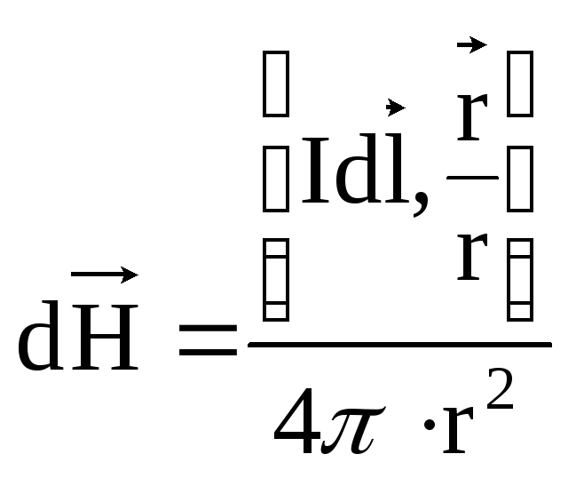
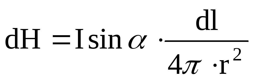
In formula (1), we select the part that does not depend on the current element I 0 dl 0 , and denote dH.
 , (2)
, (2)
Biot-Savart-Laplace law
dH depends only on the current element idl and from the position of the point ABOUT, is called magnetic field strength.
This is a vector quantity directed tangentially to the field lines and normal to the plane Q.
The tension is measured in
A field whose intensity is the same everywhere is called homogeneous, otherwise - heterogeneous.
Let's rewrite Ampère's law taking into account the intensity
ampere formula
where β is the angle between current directions I 0 and magnetic field dH.
Determine the direction of the force dF according to the left hand rule. If the palm of the left hand is positioned so that the magnetic field vector enters the palm, and the four extended fingers are directed along the current, then the thumb set aside will show the direction of the force acting on this current.
Since β = 90º, (since I 0 dl 0 perpendicular to the magnetic field), we rewrite formula (3), express from it dH
 . (4)
. (4)
physical meaning: the magnetic field strength is directed tangentially to the field line of force, and in absolute value it is equal to the ratio of the force with which the field acts on a unit current element located perpendicular to the field in vacuum to the magnetic constant.
To calculate the total tension H magnetic field, it is necessary to geometrically summarize the elementary intensities dH.
If the conductor is located in the same plane, the tension is calculated by the formula (from formula 2)
 . (5)
. (5)
All substances placed in a magnetic field acquire magnetic properties, that is, they become magnetized.
It turns out that some substances weaken the external field, while others strengthen it.
Substances that weaken the magnetic field are called diamagnetic, amplifying - paramagnetic (diamagnets and paramagnets).
Among paramagnets, a group of substances stands out, causing a very large increase in the external field. These substances are called ferromagnets.
Diamagnets- phosphorus, sulfur, antimony, carbon, many metals (bismuth, mercury, gold, silver, copper, etc.), most chemical compounds (water and almost all organic compounds).
Paramagnets– some gases (oxygen, nitrogen) and metals (aluminum, tungsten, platinum, alkali and alkaline earth metals).
ferromagnets- iron, nickel, cobalt, gadolinium and dysprosium, as well as some alloys and oxides of these metals, manganese and chromium alloys.
Causes of dia-, para- and ferromagnetism.
In atoms and molecules of any substance there are circular currents formed by the movement of electrons in orbits around nuclei - orbital currents.
Each orbital current corresponds to a magnetic moment.
In addition, electrons have their own or spin magnetic moment (English spin - rotation). The nucleus of an atom also has its own magnetic moment.
The geometric sum of the orbital and spin magnetic moments of electrons and the intrinsic magnetic moment of the nucleus forms the magnetic moment of an atom (molecule) of a substance.
For diamagnetic substances, the total magnetic moment of an atom (molecule) is equal to 0 .
Since the orbital, spin and nuclear moments cancel each other out.
However, under the influence of an external magnetic field, a magnetic moment is induced in these atoms, directed towards the opposite external field. As a result, the diamagnetic medium becomes magnetized and creates its own magnetic field, directed oppositely to the external one and therefore weakening it.
The magnetic moments of diamagnets are conserved as long as there is an external field. When the field is eliminated, the diamagnet is demagnetized.
In a paramagnet, the orbital, spin, and nuclear magnetic moments do not cancel each other out. Therefore, the atoms of the paramagnet Always have a magnetic moment. However, they are located randomly and therefore the paramagnetic medium does not exhibit magnetic properties.
The external field rotates the atoms of the paramagnet so that their magnetic moments are set predominantly in the direction of the field. (Complete orientation is prevented by thermal motion atoms).
As a result, the paramagnet is magnetized and creates its own magnetic field, coinciding in direction with the external one and amplifying it.
When the external field is eliminated, the paramagnet is demagnetized.
If in empty space there is a magnetic field with strength H, then when the space is filled with a homogeneous medium, the resulting strength is equal to
 , (6)
, (6)
where ΔН is the field strength created by the medium itself ("+" is the paramagnetic medium; "–" is the diamagnetic medium) is proportional to the external field strength. Therefore, formula (6) can be rewritten in the form
 , (7)
, (7)
where μ is a dimensionless coefficient of proportionality, called the relative magnetic permeability of the medium.
vacuum has μ =1,
for diamagnets μ
for paramagnets μ > 1.
According to Ampère's law, for a section of conductor with a length Δ l, through which current flows I, from the side of the external magnetic field strength H force is acting
 , (8)
, (8)
Ampère's law
where α is the angle between the directions of the current and the magnetic field strength.
Let us now find an expression for the force acting from the magnetic field on a moving charge. To do this, we use the Ampère formula. Current strength I is numerically equal to the charge transferred per unit time through cross section conductor.
If the value of a single charge e, and the number of charges transferred through the cross section of the conductor per unit time is equal to n, That I= en, hence,
 , (9)
, (9)
where n 0 is the number of moving charges per unit volume;
ν is their speed;
S is the cross-sectional area.
Hence,
 . (10)
Substitute (9) into (8)
 . (11)
This force acts on a section of the conductor, length Δ l, therefore, it is equal to the sum of the forces acting on all charges moving in the considered section of the conductor. The number of these charges
 . (12)
Force acting on a charge
 . (13)
 . (14)
Lorentz formula
The Lorentz formula gives the desired force acting on a charge moving at a speed ν in a magnetic field of intensity H.
In the case of a positive charge, the direction of the Lorentz force is determined by the rule of the left hand: if the fingers folded together are placed in the direction of the charge, and the palm is positioned so that the lines of the magnetic field enter the palm, then the force Δ F will be directed from the side of the retracted thumb.
When a negative charge moves, this force is directed in the opposite direction.
magnetic field called one of the parts of the electromagnetic field. Its peculiarity is that this field is created by conductors with currents, moving electrically charged particles and bodies, as well as magnetized bodies and an alternating electric field.
A magnetic field that does not change over time is called stationary.
The appearance of a magnetic field can be seen from the experiment of Ørstrede.
If a magnetic needle that can freely rotate around a vertical axis is placed under a straight conductor with direct current, then it tends to be perpendicular to the conductor with current.
The greater the current strength, the closer the arrow to the conductor and the less the influence of the Earth's magnetic field, the more accurately the arrow will be located.
The magnetic field acts only on moving particles and bodies that have electric charge. A magnetic field acts on magnetized bodies, regardless of whether they are moving or stationary.
The force characteristic of the magnetic field is the vector magnetic inductionIN .
 , (15)
where is the resulting tension;
H is the strength of the external magnetic field.
Since the magnetic field in a substance is usually characterized by a non-resultant strength H`, and the value IN(magnetic induction), then
 . (16)
Dimension of induction.
Thus,  .
.
Direction of the induction vector IN coincides with the tension vector H in a homogeneous isotropic medium.
1 T is the magnetic induction of such a uniform magnetic field that acts with a force of 1N on straight conductor 1m long with a current of 1A, located perpendicular to the field.
Mutual induction. Transformer.
The phenomenon of mutual induction consists in the occurrence of an induced field in conductors located in the vicinity of other conductors with currents that change over time.
So, if the current I 1 in contour 1 changes, then in the circuit 2 , which does not contain a current source, an induced field arises, characterized by an EMF of mutual induction. An inductive current is created, which is detected by a galvanometer.
According to Faraday's law
 , (17)
where ε 21 - EMF induction in the second circuit;
Ф 21 - the flux of magnetic induction, which is created by the magnetic field of the current I 1 and permeates the surface area covered by the contour 2 .
 , (18)
where M 21 is a coefficient, which is called the mutual inductance of the second and first circuits. Depends on sizes geometric shape And relative position contours 2 And 1 , relative magnetic permeability of the medium.
The effect of a transformer is based on the phenomenon of mutual induction, which is used to increase or decrease the voltage of alternating current.
On the core, consisting of individual plates assembled in a closed frame, there are 2 windings - primary S 1 and secondary S 2 with the number of turns respectively N 1 And N 2 . Alternating current I 1 creates an alternating magnetic field in the primary winding, which is the cause of the mutual induction EMF in the secondary winding.
When the transformer is idling, when there is no current in the secondary winding (I 2 \u003d 0), the ratio of the absolute values of the voltages U 2 And U 1 , at the ends of the secondary and primary windings is called the transformation ratio
 . (19)
For step-up transformer N 2 > N 1 , lowering - N 2 N 1 . During the working stroke, the power is equal.
A magnetic field is inextricably linked with the current, it appears and disappears along with the appearance and disappearance of the current, therefore, part of the energy of the electric field goes to create a magnetic field.
The magnetic field must have an energy equal to the work expended by the current to create this field or to create a flux of magnetic induction associated with the current.
Phenomenon electromagnetic induction is based on the mutual transformations of the energies of the electric field and magnetic field.


