The simplest figure of the hundred-yang shi-ri-na will help us in drilling square holes. If you move the center of this “triangle” along a certain trajectory, then its vertices are drawn almost like a square, and the he will sweep the entire area inside the radiant figure.
The edges of the best figure, except for small pieces in the corners, will be strictly straight ! And if you continue to live from the cutting, then you will see the corners, then the result will be exactly a square.
In order to be described above, the center of the triangular Re-lo needs to be moved along the trajectory, clearly la-yu-shchey-glue-coy from four one-to-one arcs of el-lip-owls. The centers of the el-lips are located at the tops of the square, and along the axis, at an angle of $45^\circ$ from-but-si-tel-but the sides of the square are equal to $k\cdot(1+1/\sqrt3)/2$ and $k\cdot(1-1/\sqrt3)/ 2$, where $k$ is the length of a hundred square meters.
Curved, rounded corners also appear as du-ga-mi el-lip-sovs with centers in the corners of squares , their half-axis is at an angle of $45^\circ$ from the sides of the square and is equal to $k\cdot(\sqrt3+ 1)/2$ and $k\cdot(1/\sqrt3-1)/2$.
The area of the invisible corners is only about 2% of the area of the entire square!
Now, if you make a drill in the form of a triangular Re-lo, then you can drill square holes with a little -go-round-the-corner-of-me, but ab-so-lyut-but straight-we're a hundred-on-mi!
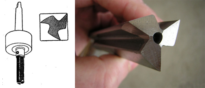
All that's left is to make that drill... Or rather, it's not difficult to make the drill itself, you just need it to fit in this is the triangle of Re-lo, and the cutting edges of the owls are with its tops.
The difficulty lies in the fact that, as already mentioned above, the tra-ek-to-ria of the center of the drill must be -one hundred of four arcs of el-lip-owls. Vi-zu-al-but this curve is very similar to a circle and even ma-te-ma-ti-che-ski close to it, but still it is not a circle ness. And all the ex-cen-tri-ki (a circle placed on a circle of another ra-di-u-sa with a shifted center), use-use- They are in tech, they allow movement strictly in a circle.
In 1914, the English engineer Harry James Watts figured out how to arrange such a drilling. On the surface he places a right-handed template with a pro-cut in the form of a square, in which a drill moves, inserted into a socket with a “free-floating drill in it.” A patent for such a pa-tron was issued to a company that started manufacturing Watts drills in 1916.
Je-ro-la-mo CARDANO (1501 - 1576). When, in 1541, im-per-ra-tor Charles V tri-um-fal-no entered the Za-vo-e-van-ny Milan, rector of the College of Vra -whose Kar-da-no was walking next to the bal-da-khin. In response to the honor, he offered to equip the royal crew with the weight of two shafts, which were not you-ve-det ka-re-tu from go-ri-zon-tal-no-go po-lo-zhe-niya […]. Justice demands to note that the idea of such a system goes back to antiquity and that at the very least in the “At-lan-ti-che-sky codex” Leo-nar-do da Vin-chi has a ri-su-nok su-do-vo-go com-pa-sa with kar -given under the weight. Such com-pa-sys in the first half of the 16th century, apparently, without influence -I-niya Kar-da-no.
S. G. Gin-di-kin. Talk about physics and ma-te-ma-ti-kah.
We are using another known structure. We attach the drill rigidly to the triangular re-lo, placing it in a square on the right-hand frame . Sam-ma ram-ka fi-si-ru-et-sya on the drill. All that remains now is to transfer the rotation of the drill to the tri-corner of Re-lo.
In some cases, it is necessary to obtain square-shaped holes. Conventional methods inefficient and heavy. The most primitive of them comes down to preliminary drilling a hole with a diameter equal to the circle inscribed in a square, and gradually punching it out. You will need a tool that can work without rotating the tool head, as well as a special adapter. It’s easier to use a so-called “square” drill (Watts drill), or, more precisely, a cutter.
Back in the 15th century, the legendary Leonardo da Vinci, studying the properties geometric shapes, drew attention to the so-called geometric objects with equal thickness. There are an infinite number of such figures, but the simplest - besides a circle - is a rounded triangle, which can be formed as follows. An equilateral triangle is drawn, each of the corners of which is connected by an arc of a circle drawn from the center of the opposite side. The peculiarity of such a triangle will be that all its sides will have a constant width, which is equal to the length of the side of the original equilateral triangle.
L. Euler drew practical benefit from this fact, who three centuries later demonstrated the rotation of such a rounded triangle: first around its own axis, and then with some eccentricity, since the cardan mechanism was already known to science and technology of that time.
The German engineer F. Relo went even further in the practical use of this figure, who drew attention to the fact that the trajectory of the corners of a moving triangle with certain methods of its rotation is very close to a square. Only directly in the corners of the square outer surface

describes an arc, however, of a small radius. In modern technical literature, such a triangle is called the Reuleaux triangle, although this figure actually no longer has any angles. A few more decades will pass, and the Englishman G. Watts will come up with a device that can provide a guaranteed square trajectory for a metal-cutting tool. Technical solution
Drill or cutter?
The majority of the technical community believes that it is still a milling cutter. However, manufacturers stubbornly continue to call this tool a drill for square holes, a Watts drill, or a drill whose profile corresponds to the Reuleaux triangle. Which is more correct? If we turn to the kinematics of movement of such a cutting tool (for clarity, you can use the diagram shown in Fig. 1), you will find that metal removal will be carried out only by the side surface, and there will be more than one cutting plane, as in regular drill
However, a single rotating motion will not be enough to obtain a square hole. Simple mathematical calculations (not given in this article) show: in order for a “drill” for a square hole to perform its function, during operation it must describe not only the basic rotational movement of the cutting edge, but also the rocking movement of the drill/cutter around a certain axis. Both movements must be made in mutual opposite directions.
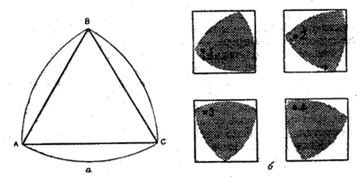
Figure 1 – Reuleaux Triangle: a) – construction; b) rotation sequence to obtain a square-shaped hole.
The angular velocity of both rotations is determined quite simply. If we take the rotation frequency of the drill shaft (or hammer drill) as the parameter f, then a speed of 0.625f is sufficient for oscillatory rotations of the spindle around its own axis. In this case, the spindle axis is, as it were, clamped between the working shaft and the drive wheel, causing the drill/cutter to oscillate clamping fixture with residual speed
(1 – 0.625)f = 0.375f.
The resulting cutter rotation speed can be determined more accurately using technical characteristics drill/hammer, but it is clear that it will be much lower than what the tool was originally designed for. Therefore, obtaining a square hole will occur with less productivity.
It is impossible to directly use a cutter/drill for square holes with a Reuleaux triangle profile - grooves are needed to remove the resulting chips.
Therefore (see Fig. 2) the profile of the working part of the tool is the figure described above, from which three half-ellipses are cut out. In this case, three goals are realized: the moment of inertia of the drill and the load on the spindle are reduced, and the cutting ability of the cutter is increased.

Figure 2 – Actual profile of the working part of the tool
The design of the tool is as follows. Actually, the working part includes a working surface used to remove metal and grooves that remove chips. A cutter-drill for square holes is made from U8 steel and hardened to a hardness of HRC 52...56. Under particularly difficult operating conditions, products made of X12 alloy steel with a hardness of HRC 56...60 are used.
With normal coolant supply and due to relatively low temperatures in the processing zone, tool life is high. More complex design

For household devices, manufacturers of cutters/drills for square holes offer overhead frames that are connected by a cardan drive to the chuck and impart eccentric movements to the cutting tool. The thickness of this frame determines the depth of the resulting hole.
To connect the device to the machine chuck, a special adapter is also required. It consists of:
For practical application For the tool in question, it is enough to give the spindle of the main equipment a feed in the required direction. Broaching milling machines and lathes are suitable for making square holes using such equipment.
//www.youtube.com/watch?v=60WbTPNFT-8
The disadvantage of Watts drills is the presence of radius arcs in the corners of the square, which is not always acceptable. In addition, square hole drills made using the Reuleaux triangle cannot handle thick workpieces.
In such cases, you can use electroerosive/laser technologies, and also, which is easier, use welding or stamping.
Matrix. To apply force to the punch, you can use hydraulic jack
. The punched hole is distinguished by the cleanliness of the resulting edges, as well as the absence of burrs. A similar tool is produced, in particular, by the Veritas trademark (Canada). If available in household welding inverter square hole
You can burn through a steel part. For this purpose, a round hole is pre-drilled (with a reserve) in the workpiece, then a square of graphite grades EEG or MPG of the required size is inserted into it, after which it is scalded along the contour. The graphite is removed, and a square hole remains in the product. If necessary, it can be cleaned and sanded. One of the main types cutting of various materials used in modern technology is drilling. It is carried out using special tool, called a drill, to which is communicated rotational movement(in some cases the workpiece rotates). By drilling you can get holes of various depths and diameters.
In most cases holes, obtained by drilling, have a cylindrical shape. However, the use of special tools and special processing techniques makes it possible to give them an ellipsoidal, square, curvilinear, oblong, triangular and other shapes.
 |
||||||||||||||||||||||||||||
| Oblong holes for fastening GOST 16030 – 70 | ||||||||||||||||||||||||||||
| D | B | L | ||||||||||||||||||||||||||
|---|---|---|---|---|---|---|---|---|---|---|---|---|---|---|---|---|---|---|---|---|---|---|---|---|---|---|---|---|
| 1st row | 2nd row | 3 | 4 | 6 | 8 | 10 | 12 | 14 | 16 | 18 | 20 | 22 | 25 | 28 | 32 | 36 | 40 | 45 | 50 | 55 | 60 | 70 | 80 | 90 | 100 | 110 | 125 | |
| 2 | 2.4 | - | × | × | × | × | ||||||||||||||||||||||
| 2.5 | 2.9 | - | × | × | × | × | ||||||||||||||||||||||
| 3 | 3.4 | - | × | × | × | × | × | |||||||||||||||||||||
| 4 | 4.5 | - | × | × | × | × | × | × | ||||||||||||||||||||
| 5 | 5.5 | - | × | × | × | × | × | × | ||||||||||||||||||||
| 6 | 6.6 | 7 | × | × | × | × | × | × | ||||||||||||||||||||
| 8 | 9 | 10 | × | × | × | × | × | × | × | × | × | × | × | |||||||||||||||
| 10 | 11 | 12 | × | × | × | × | × | × | × | × | × | × | × | |||||||||||||||
| 12 | 13 | 14 | × | × | × | × | × | × | × | × | × | × | × | |||||||||||||||
| 14 | 15 | 16 | × | × | × | × | × | × | × | × | × | × | × | |||||||||||||||
| 16 | 17 | 18 | × | × | × | × | × | × | × | × | × | × | × | |||||||||||||||
| 18 | 19 | 20 | × | × | × | × | × | × | × | × | × | × | × | |||||||||||||||
| 20 | 22 | 24 | × | × | × | × | × | × | × | × | × | × | × | |||||||||||||||
| 22 | 24 | 26 | × | × | × | × | × | × | × | × | × | × | × | |||||||||||||||
| 24 | 26 | 28 | × | × | × | × | × | × | × | × | × | × | × | |||||||||||||||
| 27 | 30 | 32 | × | × | × | × | × | × | × | × | × | × | × | |||||||||||||||
| 30 | 33 | 35 | × | × | × | × | × | × | × | × | × | × | × | |||||||||||||||
| 36 | 39 | 42 | × | × | × | × | × | × | × | × | × | × | ||||||||||||||||
| 42 | 45 | 48 | × | × | × | × | × | × | × | × | × | |||||||||||||||||
| 48 | 52 | 56 | × | × | × | × | × | × | × | |||||||||||||||||||
| Square holes for fastening GOST 16030 – 70 | ||||
 |
Square size bolt headers |
B | R | |
|---|---|---|---|---|
| 1st row | 2nd row | |||
| 5 | 5.5 | - | 0.5 | |
| 6 | 6.6 | 7 | 0.5 | |
| 8 | 9 | - | 0.8 | |
| 10 | 11 | 12 | 0.8 | |
| 12 | 13 | 14 | 1.0 | |
| 14 | 15 | 16 | 1.0 | |
| 16 | 17 | 18 | 1.2 | |
| 20 | 22 | 24 | 1.2 | |
| 22 | 24 | 26 | 1.6 | |
| 24 | 26 | 28 | 1.6 | |
Laser processing
In the conditions of modern engineering and any other production, there is often a need to obtain various materials holes having a very complex shape. A method often used for this is to use a laser beam operating in a controlled thermal splitting mode.
Today, laser processing is one of the most advanced methods of forming and processing square, oblong and others holes in a wide variety of materials. This technology allows for high-quality processing, which creates conditions for its larger-scale use.
The use of laser equipment with numerical control allows not only to manufacture or process holes a variety of shapes and configurations, but also to obtain completely finished products.
Electroerosive processing methodIn technology, electrical erosion refers to the destruction of the surface of a product or workpiece, which occurs under the influence of electrical discharges.

This processing method is most often used to change, within certain limits, the size and shape of holes previously made in metal products and workpieces. Developers of mechanical engineering products that they design are often faced with the need to manufacture holes that may be different from cylindrical. It can be square, oblong, rectangular, curved and others holes.
It is especially difficult to process them when the material itself has characteristics such as increased hardness or high viscosity. It is in these cases that electrical discharge machining is usually used.
As practice shows, it is most effective for processing products of complex configurations made of hard materials. The fact is that the use of common mechanical methods often results in increased wear of the cutting tool.
Tapered drill bits for drilling sheet metalIn thin sheet metal Quite often you have to do various holes cylindrical shape. This happens, for example, when you need to produce electric installation work in steel boxes, and this is often not so easy to do.
Drilling holes in thin sheet metal using conventional twist drills is not an easy task, since the tool begins to, as they say, “pick up”. This can (and often does) lead to its breakdown, as well as to the fact that the holes are of an irregular, curved shape. Cone drills and step drills cope with this task much better.
The fact is that, thanks to their specific shape, the layer of processed material is cut evenly, without so-called “picking up” and jerking. Therefore, the drilled holes have a perfectly cylindrical shape.
Depending on what geometric characteristics it has cutting tool, the use of drills with a conical cutting edge allows you to obtain resulting diameters of various sizes. If drilling conditions are particularly difficult, then experienced craftsmen Step drills are used instead of conical ones. This cutting tool allows for very precise dimensions of the resulting holes.
Punching holesOne of the most common technologies for sheet metal stamping is punching. For example, in such high-precision production as instrument making, a very significant number of parts are manufactured using this method. For punching square and oblong holes special equipment is used, made of high-strength materials, resistant to long-term and constant mechanical loads and does not require frequent and thorough maintenance.
Punching holes can be done both on complex mechanized equipment and on simple hand presses. Its procedure is that a workpiece is placed between the punch and the matrix, in which a hole must be punched.
As a rule, problems with the formation of round holes in metal do not arise. Today you can find a huge number of drills on sale, some can be used to form a square or rectangle. To solve this problem, special devices are also used.
Square holes are often obtained by using milling cutters. This type of tool has become extremely widespread, but in some cases it is easier to get square holes in metal using drills. Let's take the following points as an example:
In addition, cutters are installed in machines, which are expensive, but conventional equipment is not suitable for drilling. This is due to the fact that the drill must move along a certain path.
The Watts square hole drill is based on the Reuleaux triangle shape. Among the features are:
It is worth considering that the resulting rectangle or square has slightly rounded corners. Devices for drilling Watts square holes should not limit the movement of the chuck with the drill, otherwise it will not be possible to obtain the shape in question. The operating principles and design of the recommended equipment allow you to create it yourself using scrap materials.
The production of radius arcs leads to a significant decrease in the quality of the resulting product. That is why the possibility of using other methods for obtaining a square hole is often considered:
There are special sets of punches on sale that can also be used in this case. The kit is a combination of the following elements.
Any hole, if it is made using a drill, has round shape and in order to make it square, you need to work hard with some filing tool. Let's look at how you can drill a square hole in metal with minimal use of a file using the example of making a convenient and reliable tap driver.


