This article describes a simple audio frequency generator, in other words, a tweeter. The circuit is simple and consists of only 5 elements, not counting the battery and button.
Description of the circuit:
R1 sets the offset to the base of VT1. And with the help of C1 feedback is provided. The speaker is the load of VT2.
Assembly:
So, we will need:
1) A complementary pair of 2 transistors, that is, one NPN and one PNP. Almost any low-power ones will do, for example KT315 and KT361. I used what I had on hand - BC33740 and BC32740.
2) Capacitor 10-100nF, I used 47nF (marked 473).
3) Trimmer resistor about 100-200 kOhm
4) Any low-power speaker. You can use headphones.
5) Battery. Almost any one is possible. Finger, or crown, the difference will only be in the generation frequency and power.
6) A small piece of foil fiberglass, if you plan to do everything on the board.
7) Button or toggle switch. I used a button from a Chinese laser pointer.
So. All parts have been collected. Let's start making the board. I made a simple surface mount board mechanically (that is, using a cutter).

So, everything is ready for assembly.
First we install the main components.
Then we solder in the power wires, a battery with a button and a speaker.

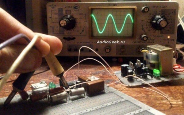
The video shows the operation of the circuit from a 1.5V battery. The tuning resistor changes the generation frequency
| Designation | Type | Denomination | Quantity | Note | Shop | My notepad |
|---|---|---|---|---|---|---|
| VT1 | Bipolar transistor | KT315B | 1 | To notepad | ||
| VT2 | Bipolar transistor | KT361B | 1 | To notepad | ||
| C1 | Capacitor | 10-100nF | 1 | To notepad | ||
| R1 | Resistor | 1-200 kOhm | 1 |
A sound wave generator is a device or electrical circuit unit responsible for creating and reproducing sound vibrations.
Where such a device can be useful:
1. A simple electric doorbell (when the contacts of a remote button are closed, a sound alert about visitors occurs);
2.Alarms (when the security system is triggered, the sound warning unit is activated);
3. Formation of a certain timbre of sound in sound equipment;
4. Repelling insects/birds (by emitting sound vibrations at certain frequencies);
5. In other professional equipment (testing low-frequency circuits, testing parts for defects and other purposes based on the properties of sound waves).
The simplest transistor sound generator
Below is a diagram with a minimum number of radio components. It can be useful for beginning radio amateurs, in radio circles, in test benches, for doorbells, etc.
In everyday life it is also called a “squeaker”.

VT1 is an n-p-n type bipolar transistor, for example, KT315. Any one will do, even low-power ones.
VT2 is bipolar, but p-n-p n type, for example, KT361. Any will do too.
Oscillations are set by a capacitor; its capacitance should be in the range of 10-100 nF.
The resistor is a tuning resistor, suitable with a value in the range of 100-200 kOhm.
Speaker BA1 should be low-power, its parameters should be comparable to the parameters of the power element. In this scheme, any available material can be used - from toys or headphones.
If the elements are arranged correctly, a printed circuit board will not be needed.
Improvement to the "game panel"
Using this scheme, you can assemble an entire panel capable of generating sound vibrations of various frequencies:
1. Since the capacitance of the capacitor is responsible for frequency generation, the number of conclusions can be made according to the number of different capacitors available (preferably in large increments so that the change in frequency is immediately noticeable to the ear.
2. One terminal of the capacitors will be common to everyone, and is connected, for example, to the base of VT1 or the speaker contact.
3. The second terminals are connected to the terminals of single galvanic contacts on the panel.
4.Now, to get sound, it is enough to include a new capacitor in the circuit only by connecting any of the output contacts to the second common point in the circuit (if the first common terminal was connected to the base of VT1, then the second to the emitter of VT2/speaker contact, or vice versa).
5.If desired, the switch can be excluded from the circuit.
As an example.

Another simple implementation is in the diagram below.

More complex scheme
If you need the ability to adjust audio frequencies within a given range, then the diagram below may be useful to you.
In light of the upcoming anniversary, for the competition " Congratulate Radio-Hobby with Morse code", we offer you two simple generators for learning and working on a telegraph key.
Simple LF generator
The circuit of a simple audio frequency (LF) generator is shown in Fig. 1. The generator circuit is assembled using transistors of different conductivities, which simplifies the circuit.

The low-frequency generator is operational with a supply voltage from 2 to 12 volts, and the desired frequency and tone are selected using resistor R1 and capacitor C1.
The range of applications of the device is varied, i.e. The low-frequency generator according to the proposed scheme can be used in various alarm systems, as well as as a sound generator for learning Morse code, etc.
radiolub.ru/page/prostoj-generator-nch
Simple generator
Quite a few audio frequency generators for studying the telegraph alphabet have been developed and described on the pages of Radio magazine. Still, the proposed generator (see diagram) will be of some interest.
Firstly, it does not have a frequency-setting capacitor. Secondly, it begins to work at a supply voltage of several tenths of a volt, even when using a transistor with a minimum transmission ratio (but not less than 10).

Generation occurs when the telegraph key SB1 is pressed due to the action of strong positive feedback between the collector and base circuits of the transistor. The sound is heard from the headphone BF1, connected to the secondary winding of the transformer. Resistor R1 sets the desired sound volume and tone.
The transistor can be any low-power silicon n-p-n structure. A p-n-p structure transistor will also work, but you will have to change the polarity of the connection of element G1. Transformer - output from any small-sized transistor receiver (for example, "Selga", "Sokol", "Almaz". "Yunost KP101". Headphone - miniature TM-2A or another similar one with a resistance of 60..300 Ohms. A DEM-4M capsule is also suitable , DEMSH, TK-67.
E. SAVITSKY, Korosten, Zhitomir region Radio, 1988, No. 3
In amateur radio practice there is often a need to use a sinusoidal oscillation generator. You can find a wide variety of applications for it. Let's look at how to create a sinusoidal signal generator on a Wien bridge with a stable amplitude and frequency.
The article describes the development of a sinusoidal signal generator circuit. You can also generate the desired frequency programmatically:
The most convenient, from the point of view of assembly and adjustment, version of a sinusoidal signal generator is a generator built on a Wien bridge, using a modern Operational Amplifier (OP-Amp).
The Wien bridge itself is a bandpass filter consisting of two. It emphasizes the central frequency and suppresses other frequencies.
The bridge was invented by Max Wien back in 1891. On a schematic diagram, the Wien bridge itself is usually depicted as follows:
Picture borrowed from Wikipedia
The Wien bridge has an output voltage to input voltage ratio b=1/3 . This is an important point, because this coefficient determines the conditions for stable generation. But more on that later
Autogenerators and inductance meters are often built on the Wien Bridge. In order not to complicate your life, they usually use R1=R2=R And C1=C2=C . Thanks to this, the formula can be simplified. The fundamental frequency of the bridge is calculated from the ratio:
f=1/2πRC
Almost any filter can be thought of as a frequency-dependent voltage divider. Therefore, when choosing the values of the resistor and capacitor, it is desirable that at the resonant frequency the complex resistance of the capacitor (Z) is equal to, or at least of the same order of magnitude as, the resistance of the resistor.
Zc=1/ωC=1/2πνC
Where ω (omega) - cyclic frequency, ν (nu) - linear frequency, ω=2πν
The Wien bridge itself is not a signal generator. For generation to occur, it must be placed in the positive feedback circuit of the operational amplifier. Such a self-oscillator can also be built using a transistor. But using an op-amp will clearly simplify life and give better performance.

The Wien bridge has a transmittance b=1/3 . Therefore, the condition for generation is that the op-amp must provide a gain of three. In this case, the product of the transmission coefficients of the Wien bridge and the gain of the op-amp will give 1. And stable generation of the given frequency will occur.
If the world were ideal, then by setting the required gain with resistors in the negative feedback circuit, we would get a ready-made generator.

This is a non-inverting amplifier and its gain is determined by the relation:K=1+R2/R1
But alas, the world is not ideal. ... In practice, it turns out that to start generation it is necessary that at the very initial moment the coefficient. the gain was slightly more than 3, and then for stable generation it was maintained at 3.
If the gain is less than 3, the generator will stall; if it is more, then the signal, upon reaching the supply voltage, will begin to distort and saturation will occur.
When saturated, the output will maintain a voltage close to one of the supply voltages. And random chaotic switching between supply voltages will occur.

Therefore, when building a generator on a Wien bridge, they resort to using a nonlinear element in the negative feedback circuit that regulates the gain. In this case, the generator will balance itself and maintain generation at the same level.
In the most classic version of the generator on the Wien bridge at the op-amp, a miniature low-voltage incandescent lamp is used, which is installed instead of a resistor.

When such a generator is turned on, at the first moment, the lamp spiral is cold and its resistance is low. This helps to start the generator (K>3). Then, as it heats up, the resistance of the spiral increases and the gain decreases until it reaches equilibrium (K=3).
The positive feedback circuit in which the Wien bridge was placed remains unchanged. The general circuit diagram of the generator is as follows:

Positive feedback elements of the op amp determine the generation frequency. And the elements of negative feedback are reinforcement.
The idea of using a light bulb as a control element is very interesting and is still used today. But, alas, the light bulb has a number of disadvantages:
Another interesting option is to use a directly heated thermistor. Essentially, the idea is the same, but instead of a light bulb filament, a thermistor is used. The problem is that you first need to find it and again select it and current-limiting resistors.
An effective method for stabilizing the amplitude of the output voltage of a sinusoidal signal generator is to use op-amp LEDs in the negative feedback circuit ( VD1 And VD2 ).

The main gain is set by resistors R3 And R4 . The remaining elements ( R5 , R6 and LEDs) adjust the gain within a small range, keeping the output stable. Resistor R5 you can adjust the output voltage in the range of approximately 5-10 volts.
In the additional OS circuit it is advisable to use low-resistance resistors ( R5 And R6 ). This will allow significant current (up to 5mA) to pass through the LEDs and they will be in optimal mode. They will even glow a little :-)
In the diagram shown above, the Wien bridge elements are designed to generate at a frequency of 400 Hz, however they can be easily recalculated for any other frequency using the formulas presented at the beginning of the article.
It is important that the operational amplifier can provide the current necessary for generation and have sufficient frequency bandwidth. Using the popular TL062 and TL072 as op amps gave very sad results at a generation frequency of 100 kHz. The signal shape could hardly be called a sinusoidal; it was more like a triangular signal. Using TDA 2320 gave even worse results.
But the NE5532 showed its excellent side, producing an output signal very similar to a sinusoidal one. LM833 also coped with the task perfectly. So it is NE5532 and LM833 that are recommended for use as affordable and common high-quality op-amps. Although, with a decrease in frequency, the rest of the op-amps will feel much better.
The accuracy of the generation frequency directly depends on the accuracy of the elements of the frequency-dependent circuit. And in this case, it is important not only that the value of the element corresponds to the inscription on it. More precise parts have better stability of values with temperature changes.
In the author's version, a resistor of type C2-13 ±0.5% and mica capacitors with an accuracy of ±2% were used. The use of resistors of this type is due to the low dependence of their resistance on temperature. Mica capacitors also have little dependence on temperature and have a low TKE.
It's worth focusing on LEDs separately. Their use in a sine generator circuit is caused by the magnitude of the voltage drop, which usually lies in the range of 1.2-1.5 volts. This allows you to obtain a fairly high output voltage.
After implementing the circuit on a breadboard, it turned out that due to the variation in LED parameters, the fronts of the sine wave at the generator output are not symmetrical. It's a little noticeable even in the above photo. In addition, there were slight distortions in the shape of the generated sine, caused by the insufficient operating speed of the LEDs for a generation frequency of 100 kHz.
The LEDs have been replaced with the beloved 4148 diodes. These are affordable, high-speed signal diodes with switching speeds of less than 4 ns. At the same time, the circuit remained fully operational, not a trace remained of the problems described above, and the sinusoid acquired an ideal appearance.
In the following diagram, the elements of the wine bridge are designed for a generation frequency of 100 kHz. Also, the variable resistor R5 was replaced with constant ones, but more on that later.

Unlike LEDs, the voltage drop across the p-n junction of conventional diodes is 0.6÷0.7 V, so the output voltage of the generator was about 2.5 V. To increase the output voltage, it is possible to connect several diodes in series, instead of one, for example like this:

However, increasing the number of nonlinear elements will make the generator more dependent on external temperature. For this reason, it was decided to abandon this approach and use one diode at a time.
Now about the tuning resistor. Initially, a 470 Ohm multi-turn trimmer resistor was used as resistor R5. It made it possible to precisely regulate the output voltage.
When building any generator, it is highly desirable to have an oscilloscope. Variable resistor R5 directly affects generation - both amplitude and stability.
For the presented circuit, generation is stable only in a small resistance range of this resistor. If the resistance ratio is greater than required, clipping begins, i.e. the sine wave will be clipped from above and below. If it is less, the shape of the sinusoid begins to distort, and with a further decrease, the generation stalls.
It also depends on the supply voltage used. The described circuit was originally assembled using an LM833 op-amp with a ±9V power supply. Then, without changing the circuit, the op amps were replaced with AD8616, and the supply voltage was changed to ±2.5V (the maximum for these op amps). As a result of this replacement, the sinusoid at the output was cut off. The selection of resistors gave values of 210 and 165 ohms, instead of 150 and 330, respectively.
In principle, you can leave the tuning resistor. It all depends on the required accuracy and the generated frequency of the sinusoidal signal.
To make your own selection, you should first of all install a tuning resistor with a nominal value of 200-500 Ohms. By feeding the generator output signal to the oscilloscope and rotating the trimming resistor, reach the moment when the limitation begins.
Then, by lowering the amplitude, find the position in which the shape of the sinusoid will be the best. Now you can remove the trimmer, measure the resulting resistance values and solder the values as close as possible.
If you need a sinusoidal audio signal generator, you can do without an oscilloscope. To do this, again, it is better to reach the moment when the signal, by ear, begins to be distorted due to clipping, and then reduce the amplitude. You should turn it down until the distortion disappears, and then a little more. This is necessary because It is not always possible to detect distortions of even 10% by ear.
The sine generator was assembled on a dual op-amp, and half of the microcircuit remained hanging in the air. Therefore, it is logical to use it under an adjustable voltage amplifier. This made it possible to move a variable resistor from the additional generator feedback circuit to the voltage amplifier stage to regulate the output voltage.
The use of an additional amplifier stage guarantees better matching of the generator output with the load. It was built according to the classic non-inverting amplifier circuit.

The indicated ratings allow you to change the gain from 2 to 5. If necessary, the ratings can be recalculated for the required task. The cascade gain is given by the relation:
K=1+R2/R1
Resistor R1 is the sum of variable and constant resistors connected in series. A constant resistor is needed so that at the minimum position of the variable resistor knob the gain does not go to infinity.
The generator was intended to operate at a low-resistance load of several ohms. Of course, not a single low-power op-amp can produce the required current.
To increase power, a TDA2030 repeater was placed at the generator output. All the goodies of this use of this microcircuit are described in the article.
And this is what the circuit of the entire sinusoidal generator with a voltage amplifier and a repeater at the output looks like:

The sine generator on the Wien bridge can also be assembled on the TDA2030 itself as an op-amp. It all depends on the required accuracy and the selected generation frequency.
If there are no special requirements for the quality of generation and the required frequency does not exceed 80-100 kHz, but it is supposed to work with a low-impedance load, then this option is ideal for you.
A Wien bridge generator is not the only way to generate a sine wave. If you need high-precision frequency stabilization, it is better to look towards generators with a quartz resonator.
However, the described circuit is suitable for the vast majority of cases when it is required to obtain a stable sinusoidal signal, both in frequency and amplitude.
Generation is good, but how to accurately measure the magnitude of high-frequency alternating voltage? A scheme called . is perfect for this.
The material was prepared exclusively for the site
Sound generator type "ZG-10"
Purpose and scope
The sound generator type "ZG-10" is a portable laboratory device designed to produce sinusoidal low-frequency alternating current voltages.
It was manufactured according to the technical specifications of TU No. 0.506.020-54 and is designed for operation at ambient temperatures from +10 to +30 degrees. C and relative humidity up to 80%.
The device type "ZG-10" is used for adjusting and testing low-frequency stages of radio equipment in laboratory and workshop practice.
Main technical characteristics
The circuit of a sound generator of the "ZG-10" type consists of the following main elements: a generator, an amplifier, an output voltage indicator, an output device and a rectifier.
The generator is a two-stage amplifier assembled on 6Zh8 and 6P9 tubes and excited by positive feedback, which is carried out by a phasing chain consisting of resistances and capacitors and providing excitation of the generator at a frequency specified by the parameters of this chain. The generator frequency is changed by changing the parameters of the phasing chain.
The generator circuit is covered by negative feedback, ensuring frequency stability and minimal nonlinear distortion.
The negative feedback circuit uses a thermistor, which acts as a nonlinear resistance to ensure that the amplitude of the generated signal remains constant.
The amplifier is assembled according to a two-stage circuit using 6N8S, 6S4S and 6S4S tubes. The first stage, assembled on a 6N8S lamp, is a bass reflex. The second stage, assembled on two 6C4C tubes, is a push-pull power amplifier.
The output voltage indicator is a tube voltmeter, designed according to the circuit of a full-wave rectifier assembled on a 6X6C lamp. An M5 type magnetoelectric device of class 2.5 is used as an indicator.
The output device consists of two dividers assembled according to a bridge and matching transformer circuit. The first divider gives an attenuation of up to 100 dB in steps of 10 dB and the second up to 10 dB in steps of 1 dB.
The matching transformer is used to match the generator output with a load of both symmetrical and asymmetrical resistance of 50, 200, 600 or 5000 Ohms.
The rectifier is assembled using a full-wave circuit using a 5Ts3S type lamp with a two-section L-shaped filter. The rectifier is powered from an alternating current network with a frequency of 50 Hz and a voltage of 110, 127 or 220 V.
Design
The device is assembled and mounted on a metal vertical panel and a horizontal chassis, placed in a metal casing equipped with handles for carrying. On the front panel of the device there are:


