Laboratory work № 8
Subject: "Determination of electromotive force and internal resistance of a current source».
Target: learn to determine the electromotive force and internal resistance of the source electrical energy.
Equipment: 1. Laboratory ammeter;
2. Source of electrical energy;
3. Connecting wires,
4. Set of resistances 2 Ohm and 4 Ohm;
5. Single-pole switch; key.
Theory.
The appearance of a potential difference at the poles of any source is the result of the separation of positive and negative charges in it. This separation occurs due to the work done by outside forces.
Forces of non-electric origin acting on free charge carriers from current sources are called outside forces.
When moving electric charges along the chain direct current external forces acting inside current sources do work.
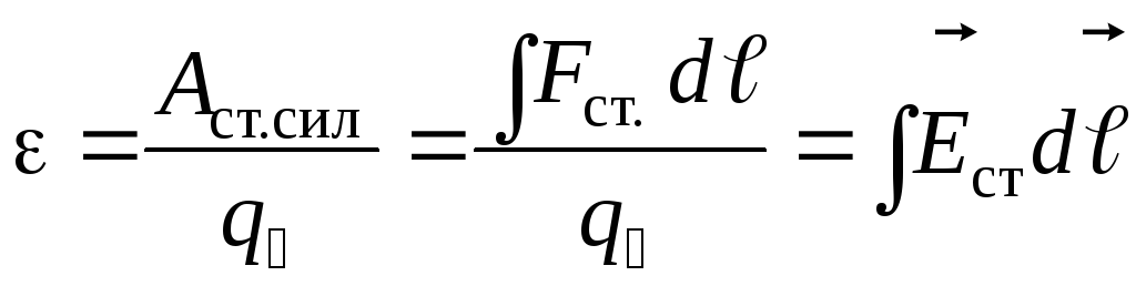
A physical quantity equal to the ratio of the work A st of external forces when moving a charge q inside a current source to the value of this charge is calledsource electromotive force (EMF):
EMF is determined by the work done by external forces when moving a single positive charge.
Electromotive force, like potential difference, is measured in volts[IN].
To measure EMF source, it is necessary join to him voltmeter with open circuit.
The current source is a conductor and always has some resistance, so the current generates heat in it. This resistance is called internal source resistance and denote r.
If the circuit is open, then the work of external forces is converted into potential energy of the current source. In a closed circuit, this potential energy is spent on work moving charges in the external circuit with resistance R and in the internal part of the circuit with resistance r, i.e. ε = IR + Ir .
If the circuit consists of an external part with a resistance R and an internal part with a resistance r, then, according to the law of conservation of energy, the emf of the source will be equal to the sum of the voltages on the external and internal sections of the circuit, because when moving along a closed circuit, the charge returns to its original position, where IR– voltage on the external section of the circuit, and Ir- voltage on the internal section of the circuit.
Thus, for a section of the circuit containing EMF:
This formula expresses Ohm's law for a complete circuit : the current strength in a complete circuit is directly proportional to the electromotive force of the source and inversely proportional to the sum of the resistances of the external and internal sections of the circuit.
ε and r can be determined experimentally.
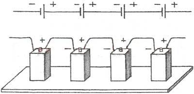
Often sources of electrical energy are interconnected to power a circuit. The connection of sources to a battery can be serial or parallel.
In a series connection, two adjacent sources are connected by opposite poles.
That is, for series connection of batteries, to the “plus” electrical diagram connect the positive terminal of the first battery. The positive terminal of the second battery is connected to its negative terminal, etc. The negative terminal of the last battery is connected to the “minus” of the electrical circuit.
The resulting battery in series connection has the same capacity as a single battery, and the voltage is the same battery equal to the sum of the voltages of the batteries included in it. Those. If the batteries have the same voltage, then the battery voltage is equal to the voltage of one battery multiplied by the number of batteries in the battery.
1. The emf of the battery is equal to the sum of the emf of individual sourcesε= ε 1 + ε 2 + ε 3
2 . The total resistance of the source battery is equal to the sum of the internal resistances of the individual sources r batteries = r 1 + r 2 + r 3
If n identical sources are connected to a battery, then the emf of the battery is ε = nε 1, and the resistance r of the battery = nr 1
3.
At parallel connection connect together all the positive and all negative poles of two orn sources.
That is, with a parallel connection, the batteries are connected so that the positive terminals of all batteries are connected to one point of the electrical circuit ("plus"), and the negative terminals of all batteries are connected to another point of the circuit ("minus").
Connect in parallel only sources With the same EMF. The resulting battery in parallel connection has the same voltage as a single battery, and the capacity of such a battery is equal to the sum of the capacities of the batteries included in it. Those. if the batteries have the same capacities, then the capacity of the battery is equal to the capacity of one battery multiplied by the number of batteries in the battery.

1. The emf of a battery of identical sources is equal to the emf of one source.ε= ε 1 = ε 2 = ε 3
2.
Battery resistance is less than single source resistance r batteries = r 1 /n
3.
Current strength in such a circuit according to Ohm's law
The electrical energy accumulated in a battery is equal to the sum of the energies of individual batteries (the product of the energies of individual batteries, if the batteries are the same), regardless of whether the batteries are connected in parallel or in series.
The internal resistance of batteries manufactured using the same technology is approximately inversely proportional to the battery capacity. Therefore, since with a parallel connection the capacity of the battery is equal to the sum of the capacities of the batteries included in it, i.e. it increases, the internal resistance decreases.
Progress.
1. Draw a table:2. Consider the ammeter scale and determine the value of one division.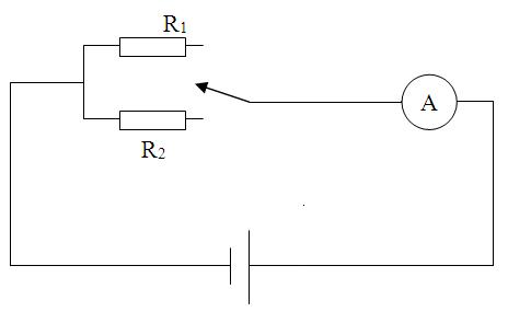
Picture 1.
4. Close the circuit by introducing a lower resistance R 1 1 . Open the circuit.
5. Close the circuit by introducing more resistance R 2 . Write down the current value I 2 . Open the circuit.
6. Calculate the value of the emf and internal resistance of the source of electrical energy.
Ohm's law for the complete circuit for each case: And
From here we obtain formulas for calculating ε and r:
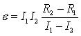
![]()
7. Write down the results of all measurements and calculations in a table.
8. Draw a conclusion.
9. Answer the security questions.
CONTROL QUESTIONS.
1. Open physical meaning the concept of “electromotive force of a current source”.
2. Determine the resistance of the external section of the circuit, using the results of the measurements obtained and Ohm's law for the complete circuit.
3. Explain why internal resistance increases when batteries are connected in series and decreases when batteries are connected in parallel compared to resistance r 0 one battery.
4. In what case does a voltmeter connected to the terminals of the generator indicate the EMF of the generator and in what case is the voltage at the ends of the external section of the circuit? Can this voltage also be considered the voltage at the ends of the internal section of the circuit?
Measurement option.
Experience 1. Resistance R 1 =2 Ohm, current I 1 =1.3 A.
Resistance R 2 =4 Ohm, current I 2 =0.7 A.
Purpose of the work: to measure the electromotive force of a current source using the compensation method.
Instruments and equipment: installation for measuring the electromotive force of a current source using the compensation method.
Theoretical mixing
Electric current is the directional movement of electric charges. Electric current is usually characterized by current strength - a scalar quantity determined by electric charges  , passing through the cross section of the conductor per unit time
  :
:
 .
(1)
.
(1)
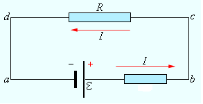
The unit of current measurement is ampere (A). If at any equal intervals of time the same amount of electricity (electric charge) passes through the cross-section of a conductor, then such a current is called constant. Conventionally, the direction of movement of positive charges is taken as the direction of the electric current in the conductor (Fig. 1a).
Physical quantity determined by the strength of current passing through a unit area cross section conductor  , perpendicular to the direction of the current, is called the current density
  :
:
 .
(2)
.
(2)
The current density is a vector  , the direction of which coincides with the ordered movement of positive charges.
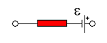
In 1826, Ohm's law was experimentally established for a homogeneous section of an electrical circuit (electrical diagram in Fig. 1b or sections ad, dc, cb in Fig. 1a), which states that the current strength in a homogeneous conductor is directly proportional to the voltage  at its ends and is inversely proportional to the resistance of the conductor
  :
:
 ,
(3)
,
(3)
|
|
|
|
The resistance of the conductor depends on the material from which the conductor is made, its linear dimensions and shape:
 ,
(4)
,
(4)
Where  - electrical resistivity characterizing the material of the conductor;
  - length of the conductor;
  - cross-sectional area of the conductor. The unit of measurement for electrical resistivity is Ohm∙m. 1 Ohm m -
This is the electrical resistivity of a conductor having an electrical resistance of 1 Ohm with a length of 1 m and a cross-sectional area of 1 m 2.
- cross-sectional area of the conductor. The unit of measurement for electrical resistivity is Ohm∙m. 1 Ohm m -
This is the electrical resistivity of a conductor having an electrical resistance of 1 Ohm with a length of 1 m and a cross-sectional area of 1 m 2.
If we substitute in expression (4) Ohm’s law for a homogeneous section of the electrical circuit (3), we obtain
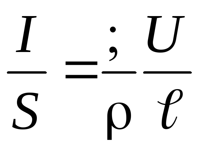 .
(5)
.
(5)
Considering that
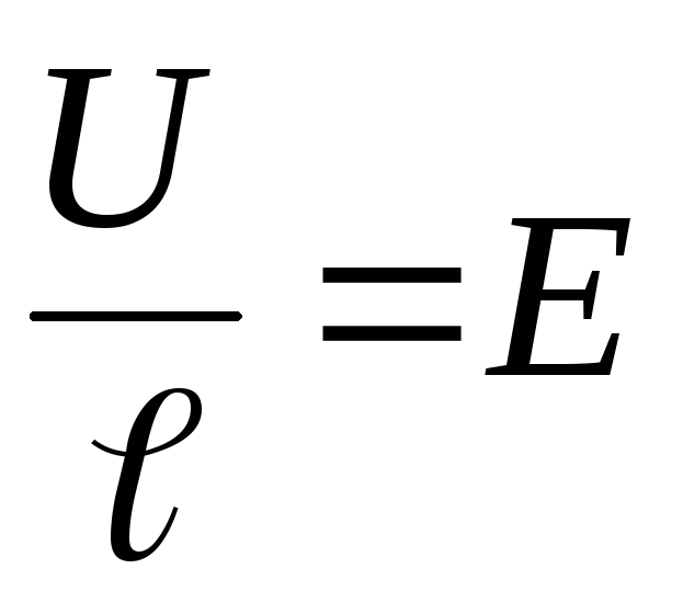 And
And 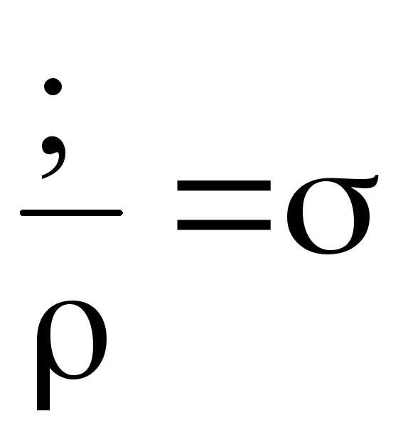 ,
,
and also applying formula (2), we transform equation (5) into an expression that represents Ohm’s law in differential form for a homogeneous section of the electrical circuit:
 ,
,
Where  - electrostatic field strength inside the conductor;
 ![]() - specific electrical conductivity of the conductor material.
- specific electrical conductivity of the conductor material.
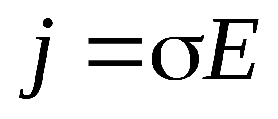
Due to the fact that positive charge carriers at each point move in the direction of the vector  , then the directions of the vectors And match up. Therefore, Ohm’s law for a homogeneous section of an electrical circuit in differential form will be written as
 .
.
In order to maintain current in a conductor for a sufficiently long time, it is necessary to continuously remove the brought positive charges from the end of the conductor with a lower potential (we consider the charge carriers positive), and to continuously bring them to the end with a higher potential, i.e. it is necessary to establish a circulation of positive charges in which they would move along a closed trajectory.
In a closed electrical circuit there are areas in which positive charges move in the direction of increasing potential, i.e. against the electrostatic field. The movement of such charges is possible only with the help of forces of non-electrostatic origin, called external. The nature of external forces is different, because their appearance is due to alternating magnetic fields, as well as chemical, diffusion, and light processes occurring in current sources.
The main characteristic of external forces is their electromotive force (EMF) - this is physical quantity, numerically equal to the work of external forces  by moving a single positive charge
  :
:
 ,
,
Where  - vector of field strength of external forces;
  - vector of charge movement. The unit of EMF measurement is V (Volt).
If the current source is connected to an external load uniformly distributed along the circuit, then the potential will decrease linearly as it moves away from the positive electrode of the battery (Fig. 2).

The transformation of electric current energy into internal energy causes heating of the conductor. J. Joule and E. Lenz experimentally established that the amount of heat released in a conductor is proportional to the square of the current in the conductor  , conductor resistance and current flow time .
 .
(6)
.
(6)
Using the Joule-Lenz law, Ohm's law was derived for a non-uniform section of an electrical circuit, which takes into account the effect of electrostatic and external forces on a moving positive charge.
According to the law of conservation of energy, the amount of heat released in a non-uniform electrical circuit (electrical diagram in Fig. 1c) is equal to the sum of the work of forces electric field and the work of third-party forces of the current source:
 ,
(7)
,
(7)
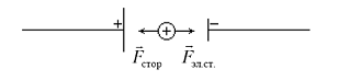
where is the work of electrostatic field forces;  - work of outside forces. External forces do positive work to move a positive charge if the directions of the external forces
  and electric current coincide (Fig. 3), otherwise the work of external forces is negative.
|
|
Considering that the total resistance in a non-uniform section of the electrical circuit is composed of the external and internal  resistance, and equating expressions (6), (7) we get
Taking into account formula (1), we transform the expression into the form:
Let us reduce the resulting expression to charge  and we obtain Ohm's law for a non-uniform section of an electrical circuit
 .
.
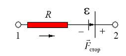
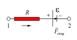
When using this law, it is necessary to take into account the rule of signs: the direction of bypassing a section of the circuit is determined by the indexation of potentials. EMF of current source  taken with a “plus” sign if the directions of external forces and bypassing a section of the electrical circuit coincide (Fig. 4a), otherwise - vice versa (Fig. 4b).
|
|
|
If the circuit is closed, i.e.  And
And  , then we obtain Ohm’s law for a closed electrical circuit (electrical diagram in Fig. 1a).
In practice, the emf of the current source cannot be measured directly using a conventional voltmeter, because a voltmeter only measures potential difference  And
And  at the source terminals. From expression (8) it follows that the emf of the current source it is possible to find through the potential difference at the source terminals (
  , if the current strength in a section of the electrical circuit is zero. This condition implemented by the compensation method. The potential difference required for compensation is obtained using a potentiometer (Fig. 5). The potentiometer is a calibrated wire wound around an insulating base, along which a contact can slide (such a device is called a rheochord). Moving the contact C from point A To B, you can get any potential difference from 0 to
  (in absolute value is always less than the EMF of the auxiliary source).
The essence of the compensation method is that the measured EMF of an unknown current source (Fig. 5) are compensated by voltage on the potentiometer section (rheochord). Compensation is achieved by moving the contact of the potentiometer C (Fig. 6) until the galvanometer D shows zero current value.

Let us denote the potential values at the ends of the rheochord by  And
And  , potentials at the ends of the current source - through And . Suppose that at a certain position of contact C on the potentiometer, the current does not flow through the galvanometer G and the current source with EMF
  , That
  And
And  , That's why
According to Ohm's law
 ,
(10)
,
(10)
Where - current strength in the potentiometer,  - resistance of the AC section.
Equating expressions (9) and (10) we get
 .
.
In order not to produce to determine the unknown EMF of the current source current measurements and resistance , resort to comparing the unknown EMF with a famous  . To do this, turn on instead of a source with EMF (Fig. 6) source with known EMF (EMF of a normal current source). Compensation is again achieved by moving the movable contact C to the zero reading of the galvanometer. As a result, the emf of the current source is determined as
 .
(11)
.
(11)
Under compensation conditions, current flows only through the circuit that includes the potentiometer. In this case, the current strength will be the same. Let us divide equalities (10) by (11), reducing by the current strength , we get the condition:
 .
(12)
.
(12)
In view of this, the potentiometer is made of a homogeneous wire, the electrical resistance of which is determined by formula (4), then we substitute this formula into expression (12) and express the emf of the current source under study
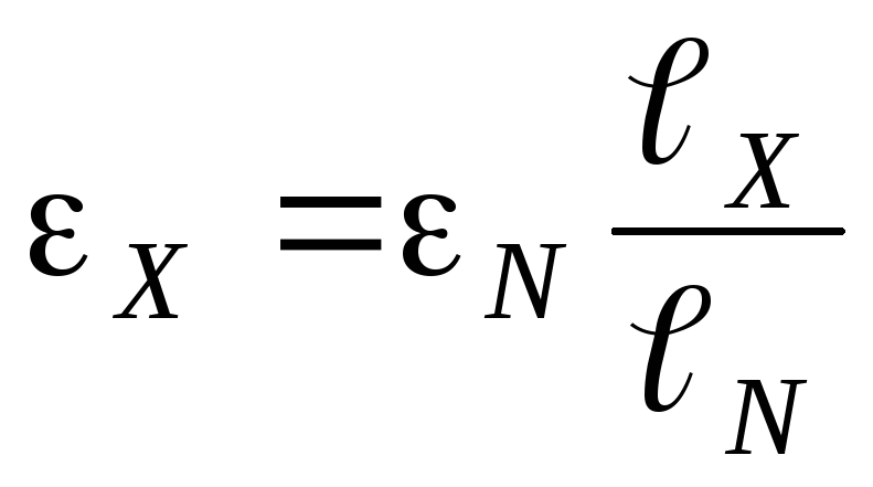 ,
(13)
,
(13)
Where ![]() And
And  lengths of sections where the EMF of an unknown current source is compensated and normal current source respectively.
It is also necessary to take into account that normal elements quickly fail when large currents are passed through them, therefore additional resistance is introduced into the galvanometer circuit, limiting the current through the normal element and the galvanometer.
Description of installation
|
|
Work order
Table 1
|
|
|
|
|
|
|
|
|
|
|
|
 ,
,
Where  ,
,
 ,
,
 - diameter of the flux wire (0.4 mm).
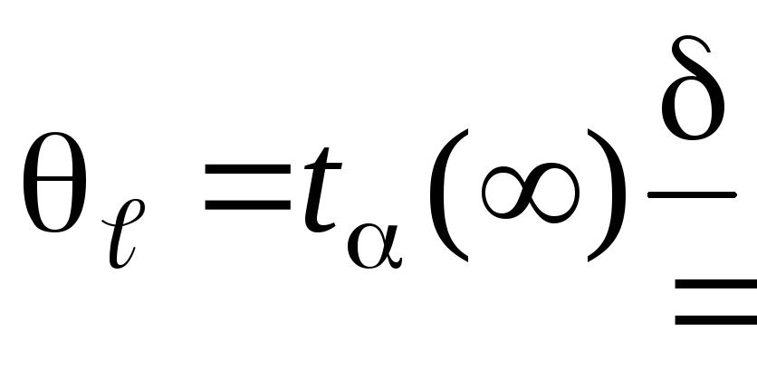
 ,
,
where is the value  indicated on the installation.
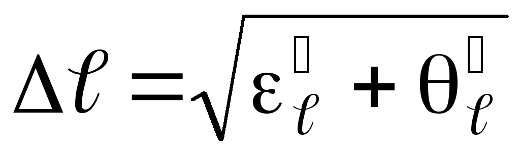
Determine the absolute measurement error for the EMF of an unknown current source using the formula
Write down the final measurement result in the form
 , at
, at  .
.
Control questions
What's happened electricity, current strength, current density?
Derive Ohm's law for a non-uniform section of an electrical circuit and obtain from it Ohm's law for a complete closed and homogeneous section of an electrical circuit.
What is the physical meaning of EMF? What are outside forces? What is their purpose?
4 How is the unknown EMF compensated when the galvanometer reaches zero reading?
5. If in the compensation circuit the source is replaced by another source with the same EMF, but with a higher internal resistance, then in which direction should the slider slide be shifted to restore compensation?
LAB WORK 5
Purpose of the work: to measure the electromotive force of a current source using the compensation method.
Instruments and equipment: installation for measuring the electromotive force of a current source using the compensation method.
Theoretical mixing
Electric current is the directional movement of electric charges. Electric current is usually characterized by current strength - a scalar quantity determined by electric charges , passing through the cross section of the conductor per unit time :
.
(1)
The unit of current measurement is ampere (A). If at any equal intervals of time the same amount of electricity (electric charge) passes through the cross-section of a conductor, then such a current is called constant. Conventionally, the direction of movement of positive charges is taken as the direction of the electric current in the conductor (Fig. 1a).
Physical quantity determined by the strength of the current passing through a unit cross-sectional area of a conductor , perpendicular to the direction of the current, is called the current density :
.
(2)
The current density is a vector , the direction of which coincides with the ordered movement of positive charges.
In 1826, Ohm's law was experimentally established for a homogeneous section of an electrical circuit (electrical diagram in Fig. 1b or sections ad, dc, cb in Fig. 1a), which states that the current strength in a homogeneous conductor is directly proportional to the voltage at its ends and is inversely proportional to the resistance of the conductor :
,
(3)
|
|
|
|
The resistance of the conductor depends on the material from which the conductor is made, its linear dimensions and shape:
,
(4)
Where - electrical resistivity characterizing the material of the conductor;
- length of the conductor; - cross-sectional area of the conductor. The unit of measurement for electrical resistivity is Ohm∙m. 1 Ohm m -
This is the electrical resistivity of a conductor having an electrical resistance of 1 Ohm with a length of 1 m and a cross-sectional area of 1 m 2.
If we substitute in expression (4) Ohm’s law for a homogeneous section of the electrical circuit (3), we obtain
.
(5)
Considering that
And ,
and also applying formula (2), we transform equation (5) into an expression that represents Ohm’s law in differential form for a homogeneous section of the electrical circuit:
,
Where - electrostatic field strength inside the conductor; ![]() - specific electrical conductivity of the conductor material.
- specific electrical conductivity of the conductor material.
Due to the fact that positive charge carriers at each point move in the direction of the vector , then the directions of the vectors And match up. Therefore, Ohm’s law for a homogeneous section of an electrical circuit in differential form will be written as
.
In order to maintain current in a conductor for a sufficiently long time, it is necessary to continuously remove the brought positive charges from the end of the conductor with a lower potential (we consider the charge carriers positive), and to continuously bring them to the end with a higher potential, i.e. it is necessary to establish a circulation of positive charges in which they would move along a closed trajectory.
In a closed electrical circuit there are sections in which positive charges move in the direction of increasing potential, i.e. against the electrostatic field. The movement of such charges is possible only with the help of forces of non-electrostatic origin, called external. The nature of external forces is different, because their appearance is due to alternating magnetic fields, as well as chemical, diffusion, and light processes occurring in current sources.
The main characteristic of external forces is their electromotive force (EMF) - this is a physical quantity numerically equal to the work of external forces by moving a single positive charge :
,
Where - vector of field strength of external forces; - vector of charge movement. The unit of EMF measurement is V (Volt).
If the current source is connected to an external load uniformly distributed along the circuit, then the potential will decrease linearly as it moves away from the positive electrode of the battery (Fig. 2).
The transformation of electric current energy into internal energy causes heating of the conductor. J. Joule and E. Lenz experimentally established that the amount of heat released in a conductor is proportional to the square of the current in the conductor , conductor resistance and current flow time .
.
(6)
Using the Joule-Lenz law, Ohm's law was derived for a non-uniform section of an electrical circuit, which takes into account the effect of electrostatic and external forces on a moving positive charge.
According to the law of conservation of energy, the amount of heat released in a non-uniform electrical circuit (electrical diagram in Fig. 1c) is equal to the sum of the work of the electric field forces and the work of external forces of the current source:
,
(7)
where is the work of electrostatic field forces; - work of outside forces. External forces do positive work to move a positive charge if the directions of the external forces and electric current coincide (Fig. 3), otherwise the work of external forces is negative.
|
|
Considering that the total resistance in a non-uniform section of the electrical circuit is composed of the external and internal resistance, and equating expressions (6), (7) we get
Taking into account formula (1), we transform the expression into the form:
Let us reduce the resulting expression to charge and we obtain Ohm's law for a non-uniform section of an electrical circuit
.
When using this law, it is necessary to take into account the rule of signs: the direction of bypassing a section of the circuit is determined by the indexation of potentials. EMF of current source taken with a “plus” sign if the directions of external forces and bypassing a section of the electrical circuit coincide (Fig. 4a), otherwise - vice versa (Fig. 4b).
|
|
|
If the circuit is closed, i.e. And , then we obtain Ohm’s law for a closed electrical circuit (electrical diagram in Fig. 1a).
In practice, the emf of the current source cannot be measured directly using a conventional voltmeter, because a voltmeter only measures potential difference And at the source terminals. From expression (8) it follows that the emf of the current source it is possible to find through the potential difference at the source terminals ( , if the current strength in a section of the electrical circuit is zero. This condition is implemented by the compensation method. The potential difference required for compensation is obtained using a potentiometer (Fig. 5). A potentiometer is a calibrated wire wound around an insulating base, along which a contact can slide (such a device is called a rheochord). Moving the contact C from point A To B, you can get any potential difference from 0 to
(in absolute value is always less than the EMF of the auxiliary source).
The essence of the compensation method is that the measured EMF of an unknown current source (Fig. 5) are compensated by voltage on the potentiometer section (rheochord). Compensation is achieved by moving the contact of the potentiometer C (Fig. 6) until the galvanometer D shows zero current value.
Let us denote the potential values at the ends of the rheochord by And , potentials at the ends of the current source - through And . Suppose that at a certain position of contact C on the potentiometer, the current does not flow through the galvanometer G and the current source with EMF , That And , That's why
According to Ohm's law
,
(10)
Where - current strength in the potentiometer, - resistance of the AC section.
Equating expressions (9) and (10) we get
.
In order not to produce to determine the unknown EMF of the current source current measurements and resistance , resort to comparing the unknown EMF with a famous . To do this, turn on instead of a source with EMF (Fig. 6) source with known EMF (EMF of a normal current source). Compensation is again achieved by moving the movable contact C to the zero reading of the galvanometer. As a result, the emf of the current source is determined as
.
(11)
Under compensation conditions, current flows only through the circuit that includes the potentiometer. In this case, the current strength will be the same. Let us divide equalities (10) by (11), reducing by the current strength , we get the condition:
.
(12)
In view of this, the potentiometer is made of a homogeneous wire, the electrical resistance of which is determined by formula (4), then we substitute this formula into expression (12) and express the emf of the current source under study
,
(13)
Where ![]() And lengths of sections where the EMF of an unknown current source is compensated and normal current source respectively.
And lengths of sections where the EMF of an unknown current source is compensated and normal current source respectively.
It is also necessary to take into account that normal elements quickly fail when large currents are passed through them, therefore additional resistance is introduced into the galvanometer circuit, limiting the current through the normal element and the galvanometer.
Description of installation
|
|
Work order
Table 1
|
|
|
|
|
|
|
|
|
|
|
|
,
Where ,
,
- diameter of the flux wire (0.4 mm).
,
where is the value indicated on the installation.
Determine the absolute measurement error for the EMF of an unknown current source using the formula
Write down the final measurement result in the form
, at .
Control questions
What is electric current, current strength, current density?
Derive Ohm's law for a non-uniform section of an electrical circuit and obtain from it Ohm's law for a complete closed and homogeneous section of an electrical circuit.
What is the physical meaning of EMF? What are outside forces? What is their purpose?
4 How is the unknown EMF compensated when the galvanometer reaches zero reading?
5. If in the compensation circuit the source is replaced by another source with the same EMF, but with a higher internal resistance, then in which direction should the slider slide be shifted to restore compensation?
LAB WORK 5

 , cm
, cm
 , cm
, cm
 , cm
, cm
 , cm
, cm