Quite often, such a nuisance occurs as a wire (cable) breaking near the plug. This happens especially often with wires that are subject to constant vibrations and movements. For example, with headphones chargers, multimeter probes and the like. We notice the gap, as a rule, only after the thing we are using stops working. And it’s actually quite difficult to notice this. If only by chance we see... The break does not occur immediately, with the exception, of course, of a rough mechanical impact. The cable braid is usually damaged first.


Price: $2,3
The probes that come with inexpensive testers (multimeters) are often not of the best quality. And sometimes they deteriorate: sometimes the wire breaks, sometimes you accidentally burn it with a soldering iron. And now, cheap disposable probes have to be thrown away and replacements have to be found.
These probes looked very solid in the photos in the store. Colored plastic, caps and plugs, good length (107 cm). The price is absolutely ridiculous.
And now I’m already printing out the parcel.

The first impression is great. Everything is very neat and beautiful. The wire is soft, silicone. The probes are simply pleasant to hold in your hands. They immediately registered on my work multimeter.

I've been using them for almost a year now. During this time, I realized that their price is quite justified.

Yes, they are beautiful, the handles are molded from two-color plastic.

There are grooves on the contacts, which is very convenient for measurements. The total resistance of the two probes is 0.9 Ohm. The caps and plugs got lost very quickly, but I don’t need them. Their main drawback is the banana connectors that are inserted into the sockets of the multimeter. They are beautifully made, filled with plastic, but they constantly lose contact.

I cut the protective plastic so that they would go deeper, but that didn't help much. The contact also fell off from time to time. I endured as long as I could. But this is very inconvenient, especially when you call many different circuits, there is no short circuit everywhere, and then you connect two probes and there is no contact there either. You understand that all the work needs to start all over again. And the question arises: “Do I need such probes if they are not trusted and constantly let me down and complicate my life?” I felt sorry for throwing them away; I was already used to them, so I decided to replace the unreliable link.

The connectors were mercilessly cut off and thrown away, and to replace them I picked up gold-plated “bananas” with a rotating slip ring. This is convenient because the connectors will not “break” the multimeter sockets when rotating and the contact should be more reliable. New connectors are inserted into the tester sockets very tightly and are fixed securely. They also have holes where you can insert the same “banana”, sometimes this can be very useful. Why did I choose these "bananas"? I just didn’t find specialized connectors for testers, but I had already used these “bananas” and I really liked them for their “tightness” in the socket and ease of rotation while maintaining excellent contact. And besides, they were bought from me a long time ago and are lying idle
In order to solder new connectors to the probes, I strip the insulation.

And here is another disappointment. Although the wire itself seems thick and solid, the twisted copper core in it is thin...

Now it’s clear why there is such resistance, the copper there is a cat crying... The quality of the wire is no good, it wouldn’t be a bad idea to change it. But the probe handles with contacts themselves are cast and non-removable. Changing the wire in such probes is the same as simply throwing them away. Therefore, I decide to leave the wire as is for now, and at my leisure look for blanks for probes and good wire and make new probes yourself.
In the meantime, we attach the new “golden” connectors to the wire. They are connected without soldering. Simply insert into the connector tube and secure with a screw.

To prevent the wire from breaking at the base of the connector, I reinforced it with heat shrink.

Then another heat shrink, shorter.

I run the clamping screw so that it can tighten easily.

And on top is the plastic part of the connector.

Here, in fact, is the result.
The first tests showed that the probes (which were far from ideal initially) began to behave noticeably better. The contact in the multimeter sockets is now quite reliable (in several months they have never popped out and the contact has never been lost), the probes themselves are movable and can be easily turned. Additional functionality has appeared in the form of additional contact holes for bananas.
Every owner of a Chinese multimeter DT830 and similar models must have encountered some inconveniences during operation that are not visible at first glance.
For example, the battery constantly drains due to the fact that they forgot to turn the switch to the off position. Or lack of backlighting, impractical wires and much more.
All this can be easily modified and the functionality of your cheap multimeter can be increased to the level of individual professional foreign models. Let's consider in order what is missing and what can be added to the operation of any multimeter without special capital costs.
Replacing multimeter wires and probes
First of all, what 99% of users of cheap Chinese multimeters encounter is the failure of low-quality measurement probes.
 Firstly, the tips of the probes may break. When touching an oxidized or slightly rusty surface for measurement, the surface must be lightly cleaned to ensure reliable contact. The most convenient way to do this is, of course, using the probe itself. But as soon as you start scraping, at that moment the tip may break off.
Secondly, the cross-section of the wires included in the kit also does not stand up to criticism. Not only are they flimsy, but this will also affect the error of the multimeter. Especially when the resistance of the probes themselves plays a significant role during measurements.
Most often, a wire break occurs at the connection points at the plug-in contact and directly at the soldering of the sharp tip of the probe. 
When this happens, you will be surprised how thin the wiring inside is really.  Meanwhile, the multimeter must be designed to measure current loads up to 10A! It is not clear how this can be done using such a wire.
Here are real current consumption measurements for flashlights, made using standard styli included in the kit and using homemade probes with a cross section of 1.5 mm2. As you can see, the difference in error is more than significant. 
The plug-in contacts in the multimeter connectors also become loose over time and worsen the overall resistance of the circuit during measurements.
In general, the unequivocal verdict of all owners of DT830 multimeters and other models is that the probes need to be modified or changed immediately after purchasing the tool. 
If you are the lucky owner lathe or you have a familiar turner, then you can make the probe handles yourself from some insulating material, for example pieces of unnecessary plastic.
The tips of the probes are made from a sharpened drill. The drill itself is a hardened metal and can be used to easily scrape off any carbon deposits or rust without the risk of damaging the probe. 
When replacing plug-in contacts, it is best to use the following plugs used in audio equipment for speaker sockets. 
If you really want to farm or there are no other options at hand, then as a last resort you can use ordinary contacts from a collapsible plug.
They also fit perfectly into the connector on the multimeter.  At the same time, do not forget to insulate the ends that will stick out outside the multimeter, in the places where the wires are soldered to the plug, with a heat pipe.
When it is not possible to make probes yourself, the body can be left the same, replacing only the wires.
In this case, three options are possible:

After replacement, such wires will very easily be collected into a bundle without getting tangled.
Secondly, they are designed to withstand a huge number of bends and will break no sooner than the multimeter itself fails.
Thirdly, the measurement error due to their larger cross-section compared to the original ones will be minimal. That is, there are continuous advantages everywhere.
If you make long wires up to 1.5 m, taking into account all the connections, the resistance on them can reach several ohms!Important note: when replacing wires, you should not try to make them much longer than those that came with the kit. Remember that the length of the wire, as well as its cross-section, affects the overall resistance of the circuit.
Those who do not want to do homemade products can order ready-made, high-quality silicone probes with many tips on AliExpress. 
To ensure that new probes with wire take up minimal space, you can twist them into a spiral. For this new wire it is wound around the tube, wrapped in electrical tape to secure it, and the whole thing is heated with a hair dryer for a couple of minutes. As a result, you get this result. 
In a cheap version, this trick will not work. And when used for heating construction hair dryer insulation may even float.
Refinement of the multimeter mount
Another inconvenience when taking measurements with a multimeter is the lack of a third hand. You constantly have to hold a multimeter in one hand and use the other to work with two probes at the same time.  If measurements take place at your desk, then there is no problem. Put the tool down, free your hands and work.
What should you do if you measure the voltage in a panel or in a distribution box under the ceiling?
The problem can be solved simply and inexpensively. In order to be able to mount the multimeter on a metal surface, on back side device using hot glue or double-sided tape, glue ordinary flat magnets. 
And your device will be no different from expensive foreign analogues. 
Another option for inexpensive modernization of a multimeter in terms of its convenient placement and installation on a surface for measurements is manufacturing homemade stand. To do this, you only need 2 paper clips and hot glue. 
And if you don’t have any surface nearby where you can place the tool, what should you do in this case? Then you can use an ordinary wide elastic band, for example from suspenders. 
You make a ring out of an elastic band, pass it through the body and that’s it. Thus, the multimeter can be conveniently mounted directly on your hand, like a watch.
Firstly, now the multimeter will never fall out of your hands again, and secondly, the readings will always be before your eyes. 
Caps for probes
The spikes at the ends of the probes are quite sharp, which can hurt you. Some models come with protective caps, some do not.  They also get lost quite often. But in addition to the danger of pricking your finger, they also protect the contacts from breaking when the multimeter is in a bag mixed with another tool.
In order not to buy spare ones every time, you can make them yourself. Take an ordinary cap from a gel pen and lubricate the tip of the dipstick with any oil. This is done so that the cap does not stick to the surface during the manufacturing process.
Then fill inner surface hot glue the cap and place it on the sharp tip.  Wait until the hot glue hardens and calmly remove the resulting result.
Multimeter backlight
A function that the multimeter lacks in poorly lit areas is display backlighting. Solving this problem is not difficult, just apply:

Make a hole in the side of the housing for the switch. Glue the reflector under the indication display and solder two wires to the crown contacts.  They supply power to the switch and then to the LEDs. The structure is ready.
The final result of a homemade modification of the multimeter backlight will look like this: 
The backlit battery will drain much faster, so be sure to turn off the switch when natural light will be quite enough.
Replacing the crown in a multimeter with a lithium-ion battery from a phone
IN last years It has become very popular to remake a multimeter by replacing the power supply from the original crown with a lithium ion battery from cell phones and smartphones. For these purposes, in addition to the battery itself, you will need charging and discharging boards. They are bought on Aliexpress or other online stores. 
The overdischarge protection board for such batteries is initially built into the battery in its upper part. It is needed to prevent the battery from being discharged beyond its nominal value. acceptable standards(about 3 Volts and below). 
The charging board does not allow the battery to be recharged above 4.2 Volts (link to aliexpress).  In addition, you will need a board that increases the voltage from 4V to the required 9V (link to aliexpress).
The battery itself fits compactly on the back cover and does not interfere with its closure. 
First, the output voltage on the boost module must be set to 9 Volts. Connect it with wires to a multimeter that has not yet been converted and use a screwdriver to unscrew the required value. 
You will have to make a hole in the case for a micro or mini USB charging connector.

The boosting module itself is located in the place where the crown should be. 
Be sure to ensure that the wiring from the module to the battery is of the required length. In the future, this will allow you to easily remove the cover and, having halved the body, carry out an internal inspection of the multimeter if necessary.
After placing all the parts inside, all that remains is to solder the wiring according to the diagram and fill everything with hot glue so that nothing moves when moving the device. 
It is advisable to fill not only the body with hot glue, but also the contacts with the wires in order to extend their service life. 
A significant drawback of such a multimeter on a lithium-ion battery is its operation, or rather not operation, at subzero temperatures.
Once your multimeter sits in the trunk of a car or in a bag in the winter for a long time, you will immediately remember the battery.
And you might think, was such a change useful? Ultimately, of course, you decide, based on the operating conditions of the device.
Refinement of the on/off button on the multimeter
It is advisable to further improve the last option for refining the multimeter with the transition to lithium-ion batteries by placing a shutdown button in the power supply circuit of the converter to the battery. 
First, the converter itself consumes a small amount of current, even in standby mode when the multimeter is not working.
Secondly, thanks to this switch, you won’t have to click the multimeter itself again to turn it off. Many devices fail prematurely because of this reason.
Some paths are erased ahead of time, others begin to shorten each other. So a button to turn off the entire device at once will be very useful.
Another tip from experienced users of Chinese multimeters is that in order for the switch to serve for a long time and properly, immediately after purchase, disassemble and lubricate the sliding areas of the switch balls. 
And on the board it is recommended to coat the tracks with technical Vaseline. Since new devices do not have lubrication, the switch wears out quickly. 
You can make a button like an internal one, if you find it free place, and in the external. To do this, you will have to drill only two micro holes for the power wiring. 
Flashlight in multimeter
Another innovation for the multimeter - additional option flashlight. Often you have to use the device to look for damage in switchboards and distribution cabinets in basements, or short circuits in wiring in rooms where there is no light.
An ordinary white LED and a button specifically for turning it on are added to the circuit. It is very easy to check how much luminous flux from a given LED is enough. You don't even have to disassemble it to do this.
Place the anode leg of the diode in connector E, and the cathode leg in connector C (the anode leg is longer than the cathode). All this is done in the connectors for the transistor measurement mode on the P-N-P block. 
The LED will glow in any position of the switch and will go out only when you turn off the multimeter yourself. To mount all this inside, you need to find the necessary pins on the circuit board and solder two wires to the emitter (connector E) and collector (connector C). A button is soldered into the wire gap and mounted through a hole in the multimeter body. 
You secure everything with hot glue and you get a portable flashlight-multimeter.
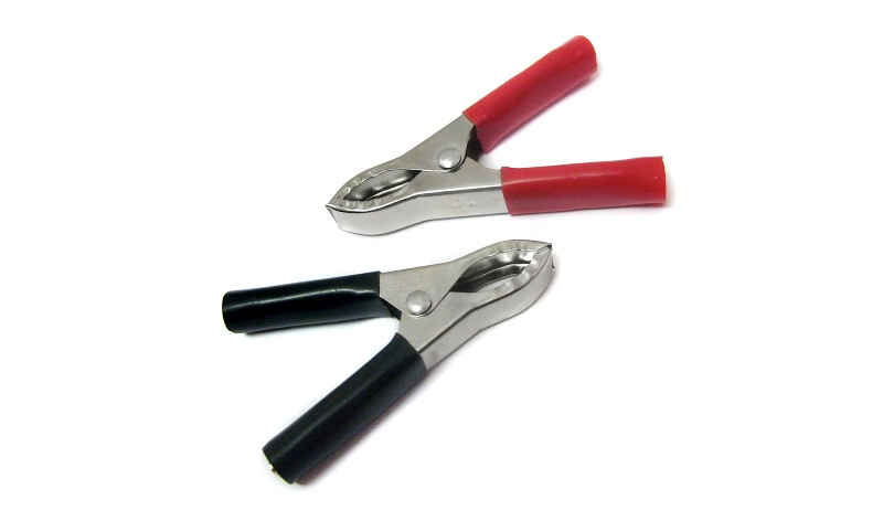
Measurements with a multimeter are made using probes. Not all multimeter probes included in the kits have good quality, so it would be preferable to make them yourself. It doesn’t take much time, but then it makes it possible not to be distracted by replacing them. It is also possible to equip the probes with crocodile clips, which will free your hands while taking measurements. Sometimes it is useful to have simultaneously measuring collapsible thin probes and a model with alligator clips, each of them will be indispensable in certain situations.
Alligator probes are very convenient to use if you need to fix a conductor for accurate measurements with a multimeter. To carry out the work you will need the following tools and components:

Wires use stranded copper because copper has good conductivity and flexibility. Silicone shells are soft, flexible, and will not break or crack over time. You can find an option specifically designed for black and red multimeters.
To make homemade probes, you need to connect the wires with plugs and clamps. If you know how to solder and have everyone necessary tools the procedure will take no more than half an hour.
 It is advisable to select the same color for the plug, wire and clamp, so that one probe is, for example, completely red, and the second completely black. In this case, the multimeter will be convenient to use and it will be easy to observe polarity when taking measurements.
First, you need to insert the wires into “bananas”, through which they will be connected to the multimeter. The connection with the plug is not particularly difficult.
A bolt is unscrewed from the banana, after which a wire can be inserted inside, the end of which has been stripped in advance. Then you need to tighten the bolt, thereby securely fixing the wire inside. The same operation is performed with the other wire. At this point, the “bananas” can be considered connected.
On at this stage strip and tin the free ends of the wires that will go to the alligator clips. Next, take a crocodile clip for a wire that matches the color. The insulation is removed from it and the bolt is unscrewed.
Clamping the wire with bolts is not the most reliable solution for multimeter probes. It will be better to solder it in this place, having first made a small soldering pad out of tin. The second “crocodile” also joins.
Now you can start soldering the crocodile. To do this, a wire is inserted inside, bringing the tinned end to the prepared area.
The wire must first be covered with crocodile insulation so that it can then be pulled over the connection.
Solder is taken and the wire is soldered to the crocodile. The soldering must be strong so that the wire does not fly off at the slightest tension. When the wire is soldered, you need to clamp it with the lower edges of the crocodile body; this can be done using pliers.
After this, strong clamps are formed, which will guarantee long-term serviceability. homemade probe. Next, the insulation is put on the crocodile. This is necessary for its reliable and safe operation, as well as for its aesthetic appearance.
You can also make thin probes for a multimeter. The cheapest and easiest option is to make them from the body of handles. Everything here is very similar, only instead of clamps you will need the following parts:
As a tip, either buy special thin probes for a dt multimeter, or use thin sewing or medical needles. It is better to use special probe needles, purchasing them on the radio market or in an online store.
Everything else you need is the same as in the previous version of making probes for a multimeter. The plugs are connected in the same way as described above, and securing the tips of future probes has several features.

To begin with, one hole is made in the top caps of the pens. This is necessary for the wire to go inside. It is desirable that their diameter matches the diameter of the wire. Next, the lower part of the handle is disassembled and a needle is inserted into it.
The needle must be soldered to the wire, which is previously inserted into the cap. The solder should not be made too thick, but it must be soldered securely. The soldering process was also discussed above.
When everything is ready, silicone is poured into the lower part of the handle and until it hardens, the needle sticks out according to the level. She should not be disturbed for several hours.
You can do it this way. First, stick the needles out 4-5 cm, then put on the cap. Thus, the tips for the probes will independently take the desired position. When the silicone has hardened, the structure is strong and comfortable.
To check the device for functionality, you need to measure the resistance of the probes. To do this, you need to connect the multimeter to the network and set the switch to measure resistance.
If the multimeter does not have automatic range adjustment, you need to switch to measuring the lowest limit.
Insert the leads of the probes into the sockets of the device, and then connect the probes to each other. The resistance figure should be 0, or as close to zero as possible. If the multimeter is automatic, then a couple of seconds after the circuit is closed, the device itself will set to 0.
If you know the sequence of the process, then all the work will not be difficult. You need to have minimal soldering skills, and then everything will be done quickly, and the device will last for many years.


