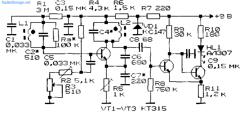
The article presents a circuit diagram of a simple but powerful 1.5 volt metal detector, very easy to replicate. The generators are assembled according to a circuit that has a number of useful properties, one of which is the stability of the output voltage (both direct and alternating) when the supply voltage changes. The oscillatory circuit of the search generator on transistor VT1 includes coil L1. It operates at a frequency of about 100 kHz, which is optimal for this type of metal detector. Its frequency can be changed within small limits using a variable capacitor C2. The second generator (on transistor VT2) is exemplary and operates at a frequency of about 300 kHz.
The generator signals through resistors R2, R4 are fed to a balanced mixer, where the difference in frequencies (beats) of the third harmonic of the search generator signal and the first harmonic of the reference generator is separated. This is done to increase sensitivity - when the frequency of the search generator changes at a frequency of 10 Hz, the beat frequency changes by 30 Hz, which is more noticeable to the ear.
The signal from the output of the mixer through capacitor C8 is supplied to the input of the ultrasonic sounder and, after amplification, to the headphones BF1, BF2. Capacitor C7 suppresses signals with generator frequencies.
When the search generator coil approaches a metal object, the generation frequency changes, therefore the tone of the signal in the headphones will also change. By the nature of the change in tone, one can judge the material from which this item is made.
Most of the parts are mounted on a printed circuit board made of single-sided foil fiberglass.
You can use transistors of the KT312, KT315, KT3102 series with any letter indices. In a balanced mixer, you can use only germanium transistors of the GT309, GT313, GT322, GT346 series or earlier - P416, P422, P423 with any letter indices. In an UZMCH, the transistor should have the highest possible current transfer coefficient, for example, KT3102BM - KT3102EM, KT342BM, KT342VM - the volume of the sound signal depends on this. Power switch - any small one. Headphones are suitable with a resistance from 8 to 32 Ohms, they are connected in series. To connect them, you can install a socket on the body of the metal detector. The device is powered by a galvanic cell or AA or AAA battery, the maximum current consumption is about 12 mA.
To wind the L2 coil, a frame from the IF circuit (455 kHz) of a foreign-made receiver is used. It consists of a ferrite “dumbbell” (on which 66 turns of PEV-2 wire with a diameter of 0.06...0.1 mm are wound) and a ferrite cup covering it, the movement of which regulates the inductance of the coil. The frame is enclosed in a metal screen.

The sensitivity of the device to metal objects of different sizes depends on the size of the search coil itself. For searching for large objects (a metal sheet measuring 80x80 cm, a manhole cover for a sewer well), a coil with a diameter of about 30 cm is more suitable. With it, a maximum detection depth of such objects is achieved up to 60 cm.
For searching for small objects, a coil with a diameter of about 120 mm is better suited. Such a coil contains 56 turns of PEL wire with a diameter of 0.2...0.5 mm.
It is more technologically feasible to make a coil of an even larger diameter (for example, 300 mm) from a multicore shielded twisted pair cable, which is used for laying computer local networks. The cable must contain four such “pairs”, and the coil must contain four turns of such cable. First, wind two outer turns and fasten them in four places with insulating tape. Then two inner ones are wound and they are also wrapped with insulating tape, preferably on a fabric basis. The ends of the cable are cut so that there is an “overlap” of 5 mm...10 mm, and the outer insulation is removed from them by 15 mm, and the ends of the wires are stripped by 5 mm and tinned.
All radio components of the device are domestic and have foreign analogues:
L1 - coil
R1 - 1 kOhm
R2 - 10 kOhm
R3 - 1 kOhm
R4 - 10 kOhm
R5 - 1 kOhm
R6 - 1 kOhm
R7 - 100 kOhm
C1 - 2200
C2 - 10...240
C3 - 4700
C4 - 0.047 µF
C5 - 2200
C6 - 4700
C7 - 0.047 µF
C8 - 2.2 uF x 16 volts
VT1 - KT315B
VT2 - KT315B
VT3 - GT322B
VT4 - GT322B
The design of a deep metal detector is similar to a regular one, with the exception of some technical details. It also differs in its increased sensitivity to metal objects, which makes it possible to detect them at greater depths compared to a simple metal detector. In addition, there is a selective search function, that is, the ability to find objects of a certain size without reacting to those that do not fit the parameters.
It is quite simple, despite its apparent complexity. The metal detector consists of two parts – receiving and transmitting. The main device is a high frequency transmitter generator. Two loop antennas, one of which serves as a signal transmitter, the second as a receiver. They must be located strictly at an angle of 90 degrees to each other to prevent the receiving antenna from picking up the generator signals. When a metal object is found, the magnetic field created by the generator is distorted and subsequently picked up by the receiving antenna. In this case, the mass of a metal object is used as a source of radiation, sending the energy produced to the receiving antenna.
Metal detector receiver circuit
The transmitting device includes a thyristor with a power of 0.25 to 1 W and a sound generator with a frequency of 200 Hz. When a metal object is found, the operator hears a sound with a frequency of 200 Hz, the strength of which depends on the size of the object found and the distance to it.
A detector receiver whose oscillation circuit responds to a frequency of 120 kHz, and consists of two diodes. The amplifier can be absolutely any low-frequency generator that can be found in an old radio. An amplifier with transistors in the amount of 5-6 pieces is enough. A transistor is also used as a current amplifier for a pointer instrument, allowing the level of the received signal to be measured. That is, the device contains two types of indicators - visual and acoustic. The operating frequency is adjusted so as not to interfere with the operation of the signal receiver.
 Transmitter circuit
To assemble such a metal detector, you must first prepare a set of necessary parts and tools.
In the case of a pulse metal detector, approximate parts list will look like this:
 Metal detector parts
From tools When performing work you will need:
The process of assembling a deep metal detector with your own hands includes the following steps:
At the first stage, it is necessary to assemble the electronic part, namely the control unit.
The step-by-step process looks like this:
The best option would be to solder everything directly, and after the setup is complete, select the necessary connectors and adapters. It is better not to twist, as this has a negative effect on the sensitivity of the device.
The second good option would be to make such a ring from twisted pair wire. You will need about 2.5 - 2.7 m of wire.
To achieve maximum sensitivity, do the following:
Upon completion of the main work, the control unit, coil and other parts are fixed in place on the rod. The metal detector can be turned on and checked.
Assembly of this type of metal detectors is not too difficult, provided all rules and instructions are strictly followed.
A device that allows you to search for metal objects located in a neutral environment, such as soil, due to their conductivity is called a metal detector (metal detector). This device allows you to find metal objects in various environments, including in the human body.
Largely thanks to the development of microelectronics, metal detectors, which are produced by many enterprises around the world, are highly reliable and have small overall and weight characteristics.
Not so long ago, such devices could most often be seen among sappers, but now they are used by rescuers, treasure hunters, and utility workers when searching for pipes, cables, etc. Moreover, many “treasure hunters” use metal detectors, which they assemble with their own hands .
Metal detectors on the market operate on different principles. Many believe that they use the principle of pulse echo or radar. Their difference from locators lies in the fact that the transmitted and received signals act constantly and simultaneously; in addition, they operate at the same frequencies.
Devices operating on the “receive-transmit” principle record the signal reflected (re-emitted) from a metal object. This signal appears due to the exposure of a metal object to an alternating magnetic field generated by the metal detector coils. That is, the design of devices of this type provides for the presence of two coils, the first is transmitting, the second is receiving.
Devices of this class have the following advantages:
At the same time, metal detectors of this class have certain disadvantages:
In other words, devices of this type must be configured with your own hands before work.
Other devices are sometimes called beat metal detectors. This name comes from the distant past, more precisely from the times when superheterodyne receivers were widely used. Beating is a phenomenon that becomes noticeable when two signals with similar frequencies and equal amplitudes are summed. The beat consists of pulsating the amplitude of the summed signal.
The signal pulsation frequency is equal to the difference in the frequencies of the summed signals. By passing such a signal through a rectifier, it is also called a detector, and the so-called difference frequency is isolated.
This scheme has been used for a long time, but nowadays it is not used. They were replaced by synchronous detectors, but the term remained in use.
A beat metal detector works using the following principle - it registers the difference in frequencies from two generator coils. One frequency is stable, the second contains an inductor.
The device is configured with your own hands so that the generated frequencies match or at least are close. As soon as metal enters the action zone, the set parameters change and the frequency changes. The frequency difference can be recorded in a variety of ways, from headphones to digital methods.
Devices of this class are characterized by a simple sensor design and low sensitivity to the mineral composition of the soil.
But besides this, when using them, it is necessary to take into account the fact that they have high energy consumption.
The metal detector includes the following components:
All devices included in the metal detector are waterproof.
It is this relative simplicity of design that allows you to make metal detectors with your own hands.
There is a wide range of metal detectors on the market, used in many areas. Below is a list that shows some of the varieties of these devices:
Most modern metal detectors can find metal objects at a depth of up to 2.5 m; special deep products can detect a product at a depth of up to 6 meters.
The second parameter is the operating frequency. The thing is that low frequencies allow the metal detector to see to a fairly large depth, but they are not able to see small details. High frequencies allow you to notice small objects, but do not allow you to view the ground to great depths.
The simplest (budget) models operate at one frequency; models that fall into the middle price range use 2 or more frequencies. There are models that use 28 frequencies when searching.
Modern metal detectors are equipped with a function such as metal discrimination. It allows you to distinguish the type of material located at depth. In this case, when ferrous metal is detected, one sound will sound in the search engine’s headphones, and when non-ferrous metal is detected, another sound will sound.
Such devices are classified as pulse-balanced. They use frequencies from 8 to 15 kHz in their work. Batteries of 9 - 12 V are used as a source.
Devices of this class are capable of detecting a gold object at a depth of several tens of centimeters, and ferrous metal products at a depth of about 1 meter or more.
But, of course, these parameters depend on the device model.
There are many models of devices on the market for detecting metal in the ground, walls, etc. Despite its external complexity, making a metal detector with your own hands is not that difficult and almost anyone can do it. As noted above, any metal detector consists of the following key components - a coil, a decoder and a power supply signaling device.
To assemble such a metal detector with your own hands, you need the following set of elements:
The metal detector circuit is not complicated, and you can find it either on the vast world wide web or in specialized literature. Above is a list of radio elements that are useful for assembling a metal detector with your own hands at home. You can assemble a simple metal detector with your own hands using a soldering iron or other available method. The main thing is that the parts should not touch the body of the device. To ensure the operation of the assembled metal detector, power supplies of 9 - 12 volts are used.
To wind the coil, use a wire with a cross-sectional diameter within 0.3 mm; of course, this will depend on the chosen circuit. By the way, the wound coil must be protected from exposure to extraneous radiation. To do this, shield it with your own hands using ordinary food foil.
To flash the controller firmware, special programs are used, which can also be found on the Internet.
If a novice “treasure hunter” has no desire to get involved with microcircuits, there are circuits without them.
There are simpler circuits based on the use of traditional transistors. Such a device can find metal at a depth of several tens of centimeters.
Deep metal detectors are used to search for metals at great depths. But it is worth noting that they are not cheap and therefore it is quite possible to assemble it yourself. But before you start making it, you need to understand how a typical circuit works.
The circuit of a deep metal detector is not the simplest and there are several options for its implementation. Before assembling it, you need to prepare the following set of parts and elements:
Nominal parameters and quantity depend on the selected circuit diagram of the device. To assemble the above elements, you will need a soldering iron, a set of tools (screwdriver, pliers, wire cutters, etc.), and material for making the board.
The process of assembling a deep metal detector looks something like this. First, a control unit is assembled, the basis of which is a printed circuit board. It is made from textolite. Then the assembly diagram is transferred directly to the surface of the finished board. After the drawing is transferred, the board must be etched. To do this, use a solution that includes hydrogen peroxide, salt, and electrolyte.
After the board is etched, it is necessary to make holes in it to install the circuit components. After tinning the board. The most important stage is coming. Do-it-yourself installation and soldering of parts onto a prepared board.
To wind the coil with your own hands, use PEV brand wire with a diameter of 0.5 mm. The number of turns and the diameter of the coil depend on the selected circuit of the deep metal detector.
There is an opinion that it is quite possible to make a metal detector from a smartphone. This is wrong! Yes, there are applications that install under Android OS.
But in fact, after installing such an application, he will actually be able to find metal objects, but only pre-magnetized ones. It will not be able to search for, much less discriminate against, metals.
Devices capable of detecting metal objects in weakly conducting environments are called metal detectors, or metal detectors. They can be used to search for ferrous and non-ferrous metals. A homemade metal detector for coins is capable of detecting small items at a distance of 10 to 50 cm, and larger metals from 0.5 to 3 m.
The use of metal detectors has been known since ancient times, and a large increase in their production occurred at the end of the 60s. Thanks to progress and a variety of schemes, any novice radio amateur can make a metal detector with his own hands, without resorting to extensive knowledge in electronics. The main advantage of homemade metal detectors is low costs.
Let's assemble a simple metal detector that operates on two frequency generators - a beat metal detector. At the same frequency, the generators are synchronized, but when one of the metal coils enters the field, the frequency in one of the generators changes. As a result, the circuit reproduces the sound of the difference in frequencies of two generators in the dynamics.
To make a homemade metal detector, you need to divide the process into three stages - creating a design, implementing a circuit, and assembling it into a single whole. We will describe an approximate list of tools and materials that may be needed for these purposes. Further on in the article, we will explain in more detail: what a metal detector for gold can be assembled from, and what kind of material is best to use. Let's start by preparing a tool for beginning diggers. To work you will need:
Necessary materials:
Detailed instructions on selecting and searching for parts are described here.
First, you need to decide on the material and fastening of the components of the metal detector and find the necessary components.
As a barbell, you can use a crutch with an armrest, a fishing rod, a pipe made of cross-linked polyethylene or polyvinyl chloride (Fig. 2).

The coils and circuitry will be placed underneath on a stand attached to the rod. So it is important to consider the stiffness of the bar and its material. It is better to give preference to dielectrics, i.e. non-conducting electric current - plastic, wood, etc. It is necessary to make a handle to make it comfortable to hold the metal detector being manufactured. In the case of a crutch, it is not needed, but in another case, you can attach either a bicycle handlebar or another homemade structure.
The stand for the circuit and coils can be made from ordinary plastic. It is easy to trim and weighs little. You will need one bottom sheet, since access to the coils is required to adjust the device. To reduce vibration of the circuit with coils, it is advisable to choose stronger plastic.
After preparing the rod and stand, you need to connect them. You can use fasteners, but do not forget that for the circuit to work properly, you should not bring metal products closer than 30 cm. Therefore, we use good glue, for example, liquid nails. You can use other materials - it all depends on your abilities in plumbing and carpentry.
The wire for the coils must be insulated. Suitable enameled copper wire with a diameter of 0.5 - 0.7 mm grade PEV or PEL. The wire length is about 100 meters. An oil-based varnish is suitable for fixing parts.
The parts can be mounted using a hinged method on PCB or cardboard. For beginning radio amateurs, in specialized stores you can buy processed textolite from the factory or material with holes for parts. You can also make a board yourself from solid unprocessed PCB. To do this, you need to mark the location of the contacts of the radio components on the diagram, then separate the sections of the textolite with a knife and tin the pads and tracks (Fig. 3). We cut off the excess part of the PCB with a plastic saw.

To assemble a working metal detector, radio components can be found at home in old radio equipment, but it is advisable to purchase them in a store. Identical parts must be completely identical and preferably from the same batch. Table 1 provides a list of necessary parts and comments, the implementation of which will lead you to assembling a high-quality metal detector.
After finding all the necessary parts, you can easily assemble the metal detector at home.


Having considered the list of necessary materials and parts, we will answer in detail how to assemble a metal detector from them with your own hands.
To wind the coils, we use any round object with a diameter of 20–25 cm. The number of turns is 30. We bring out one end of the wire and wind it 10 turns, after which, without breaking it, we bring out the second end. We continue winding another 20 turns and bring out the third end. We make the wire leads with a margin of 10 to 20 cm. Remove the resulting winding from the object and wrap it tightly with electrical tape, leaving three wire leads (Fig. 5).

We perform the second coil in a similar way. For the greatest success, we make the coils as identically as possible, with a mirror image.
Let's start assembling the radio components. We arrange the parts on the board and carry out soldering according to the diagram in Figure 4. When using cardboard or material with holes, we connect the parts with insulated wires of any cross-section. When using prepared PCB, we perform soldering to the finished tracks. The circuit can be placed in a wooden or plastic box.
Solder the coil leads according to the diagram. We solder and bring out two wires with a connector for the battery.

We prepare a stand for the circuit and coils. We select the dimensions taking into account that the distance between the coils must be at least 10 cm, since the circuit and the attached rod must fit between them.
To properly secure the coils, temporarily attach the headphones to the circuit and insert the battery. By slightly moving the coils, we achieve silence in the headphones with single clicks or the highest possible, barely audible sound. We try to bring metal to one of the coils, if we hear significant changes, this indicates the functionality of the metal detector. We fix the coils and the board in this position. If possible, it is better to glue them immediately and then cover them with oil varnish.
For headphones, we make two holes in the rod - bottom and top. Using wire cutters, electrical tape and a soldering iron, we extend the headphone wire to the required length - from the circuit to the human ear area. You need to take growth into account right away. We stretch the wire inside the rod and solder it to the circuit.
We cut off the excess stand and attach the bar to it in a way convenient for you.

The most accurate setting is the absence of clicks in the headphones, and the presence of a barely audible high-frequency squeak.
Adjustment is carried out in three ways:
With good hearing and experience, you can use the manufactured metal detector as a simple metal detector with discrimination, that is, with recognition of types of metal.
If you have figured out how to make the simplest metal detector with your own hands, you can proceed with a small modernization without microcircuits in Figure 9. The list of parts is collected in Table 2.


The new circuit adds an RC circuit consisting of a resistor and a capacitor. It will allow you to achieve increased sensitivity.
Variable resistors have been added to adjust the circuit without touching the coils. This will seal the sensitive unit of the metal detector in a durable box that protects it from shock.
Instead of headphones, you can use a speaker with a capacitor to increase the volume slightly.
In this scheme, the coils are placed one on top of the other, as shown in Figure 10. Before fixing the coils, we adjust them by moving them.

When turned on, we set the variable resistors to the same position and by rotating we achieve precise adjustment. After that, all that remains is to take a metal detector and go in search of nuggets or metals. Tested in practice - if you search on any Russian beach, you can find gold and silver.
Do-it-yourself metal detector - as the name suggests, such devices are made independently and are designed to search for metal objects and are used for a fairly narrow purpose. However, the methods for their implementation are quite diverse and constitute a whole direction in radio electronics.
The metal detector according to N. Martynyuk’s scheme (Fig. 1) is made on the basis of a miniature radio transmitter, the radiation of which is modulated by an audio signal [Рл 8/97-30]. The modulator is a low-frequency generator made according to the well-known symmetrical multivibrator circuit.
The signal from the collector of one of the multivibrator transistors is fed to the base of the high-frequency generator transistor (VT3). The operating frequency of the generator is located in the frequency range of the VHF-FM broadcast range (64... 108 MHz). A piece of television cable in the form of a coil with a diameter of 15...25 cm was used as the inductor of the oscillating circuit.
Rice. 1. Schematic diagram of N. Martynyuk’s metal detector.
If a metal object is brought closer to the inductor of the oscillating circuit, the generation frequency will noticeably change. The closer the object is brought to the coil, the greater the frequency shift will be. To record frequency changes, a conventional FM radio receiver is used, tuned to the frequency of the HF generator.
The receiver's automatic frequency control system should be disabled. If there is no metal object present, a loud beep is heard from the receiver's speaker.
If you bring a piece of metal to the inductor, the generation frequency will change and the volume of the signal will decrease. The disadvantage of the device is its reaction not only to metal, but also to any other conductive objects.
In Fig. 2 - 4 shows a circuit of a metal detector with a different operating principle, based on the use of a low-frequency LC oscillator and a bridge frequency change indicator. The search coil of the metal detector is made in accordance with Fig. 2, 3 (with correction of the number of turns).

Rice. 2. Metal detector search coil.

Rice. 3. Metal detector search coil.
The output signal from the generator is fed to a bridge measuring circuit. A high-resistance telephone capsule TON-1 or TON-2 is used as a bridge null indicator, which can be replaced with a pointer or other external alternating current measuring device. The generator operates at frequency f1, for example, 800 Hz.
Before starting work, the bridge is balanced to zero by adjusting the capacitor C* of the oscillating circuit of the search coil. The frequency f2=f1 at which the bridge will be balanced can be determined from the expression:

Initially, there is no sound in the telephone capsule. When a metal object is introduced into the field of the search coil L1, the generation frequency f1 will change, the bridge will become unbalanced, and a sound signal will be heard in the telephone capsule.

Rice. 4. Diagram of a metal detector with an operating principle based on the use of a low-frequency LC generator.
The bridge circuit of a metal detector using a search coil that changes its inductance when metal objects approach is shown in Fig. 5. An audio frequency signal from a low-frequency generator is supplied to the bridge. Using potentiometer R1, the bridge is balanced for the absence of an audio signal in the telephone capsule.

Rice. 5. Bridge circuit of a metal detector.
To increase the sensitivity of the circuit and increase the amplitude of the bridge unbalance signal, a low-frequency amplifier can be connected to its diagonal. The inductance of the L2 coil should be comparable to the inductance of the L1 search coil.
A metal detector operating in conjunction with a mid-wave superheterodyne radio broadcast receiver can be assembled according to the circuit shown in Fig. 6 [R 10/69-48]. The design shown in Fig. 1 can be used as a search coil. 2.

Rice. 6. A metal detector operating in conjunction with a superheterodyne radio receiver in the CB range.
The device is a conventional high-frequency generator operating at 465 kHz (the intermediate frequency of any AM broadcast receiver). The circuits presented in Chapter 12 can be used as a generator.
In the initial state, the frequency of the HF generator, mixing in a nearby radio receiver with the intermediate frequency of the signal received by the receiver, leads to the formation of a difference frequency signal in the audio range. When the generation frequency changes (if there is metal in the field of action of the search coil), the tone of the sound signal changes in proportion to the amount (volume) of the metal object, its distance, and the nature of the metal (some metals increase the generation frequency, others, on the contrary, lower it).

Rice. 7. Scheme of a simple metal detector using silicon and field-effect transistors.
The diagram of a simple metal detector is shown in Fig. 7. The device uses a low-frequency LC generator, the frequency of which depends on the inductance of the search coil L1. In the presence of a metal object, the generation frequency changes, which can be heard using the BF1 telephone capsule. The sensitivity of such a scheme is low, because It is quite difficult to detect small changes in frequency by ear.
A metal detector for small quantities of magnetic material can be made according to the diagram in Fig. 8. A universal head from a tape recorder is used as a sensor for such a device. To amplify weak signals taken from the sensor, it is necessary to use a highly sensitive low-frequency amplifier, the output signal of which is fed to the telephone capsule.

Rice. 8. Diagram of a metal detector for small quantities of magnetic material.
A different method of indicating the presence of metal is used in the device according to the diagram in Fig. 9. The device contains a high-frequency generator with a search coil and operates at frequency f1. To indicate the signal magnitude, a simple high-frequency millivoltmeter is used.

Rice. 9. Schematic diagram of a metal indicator.
It is made on diode VD1, transistor VT1, capacitor C1 and milliammeter (microammeter) PA1. A quartz resonator is connected between the output of the generator and the input of the high-frequency millivoltmeter. If the generation frequency f1 and the frequency of the quartz resonator f2 coincide, the needle of the device will be at zero. As soon as the generation frequency changes as a result of introducing a metal object into the field of the search coil, the needle of the device will deviate.
The operating frequencies of such metal detectors are usually in the range of 0.1...2 MHz. To initially set the generation frequency of this and other devices of similar purpose, a variable capacitor or a tuning capacitor connected in parallel with the search coil is used.
In Fig. Figure 10 shows a typical diagram of the most common metal detector. Its operating principle is based on the frequency beats of the reference and search oscillators.

Rice. 10. Diagram of a metal detector with two generators.

Rice. 11. Schematic diagram of the generator block for a metal detector.
A similar node, common to both generators, is shown in Fig. 11. The generator is made according to the well-known “three-point capacitive” circuit. In Fig. Figure 10 shows a complete diagram of the device. The design shown in Fig. 1 is used as search coil L1. 2 and 3.
The initial frequencies of the generators must be the same. The output signals from the generators through capacitors C2, SZ (Fig. 10) are fed to a mixer that selects the difference frequency. The selected audio signal is fed through the amplifier stage on transistor VT1 to the telephone capsule BF1.
The metal detector can also operate on the principle of disrupting the generation frequency. The diagram of such a device is shown in Fig. 12. If certain conditions are met (the frequency of the quartz resonator is equal to the resonant frequency of the oscillatory LC circuit with the search coil), the current in the emitter circuit of transistor VT1 is minimal.
If the resonant frequency of the LC circuit changes noticeably, the generation will fail, and the readings of the device will increase significantly. It is recommended to connect a capacitor with a capacity of 1 ... 100 nF in parallel to the measuring device.

Rice. 12. Circuit diagram of a metal detector that works on the principle of disrupting the generation frequency.
Metal detectors, designed to search for small metal objects in everyday life, can be assembled according to those shown in Fig. 13 - 15 schemes.
Such metal detectors also operate on the principle of generation failure: the generator, which includes a search coil, operates in a “critical” mode.
The operating mode of the generator is set by adjusted elements (potentiometers) so that the slightest change in its operating conditions, for example, a change in the inductance of the search coil, will lead to disruption of the oscillations. To indicate the presence/absence of generation, LED indicators of the level (presence) of alternating voltage are used.
Inductors L1 and L2 in the circuit in Fig. 13 contain, respectively, 50 and 80 turns of wire with a diameter of 0.7...0.75 mm. The coils are wound on a 600NN ferrite core with a diameter of 10 mm and a length of 100... 140 mm. The operating frequency of the generator is about 150 kHz.

Rice. 13. Circuit of a simple metal detector with three transistors.

Rice. 14. Scheme of a simple metal detector using four transistors with light indication.
Inductors L1 and L2 of another circuit (Fig. 14), made in accordance with the German patent (No. 2027408, 1974), have 120 and 45 turns, respectively, with a wire diameter of 0.3 mm [P 7/80-61 ]. A 400NN or 600NN ferrite core with a diameter of 8 mm and a length of 120 mm was used.
A household metal detector (HIM) (Fig. 15), previously produced by the Radiopribor plant (Moscow), allows you to detect small metal objects at a distance of up to 45 mm. The winding data of its inductors are unknown, however, when repeating the circuit, you can rely on the data given for devices of similar purposes (Fig. 13 and 14).
Rice. 15. Scheme of a household metal detector.
Literature: Shustov M.A. Practical circuit design (Book 1), 2003


