Platform: AutoCAD, nanoCAD, BricsCAD
The program is intended for designing cable duct systems, fire alarm, systems burglar alarm, access control and management systems in the AutoCAD/nanoCAD environment. Combines a convenient, intuitive interface and tools for graphical display and equipment calculations.
Specialized software is the second tool for low-current designers, developed taking into account the main standards SP 5.13130.2009, RD 25.953–90, RD 78.36.002–99, RM 78.36.001–99, NPB 160–97, GOST 21.1101–2009 .
The software product allows you to solve the following problems:
The program implements a Project Manager. With its help, all basic operations are performed with documents included in the project (creation, loading, adding, deleting), it establishes the execution of individual documents, and views and edits documents. Using the Project Manager, you can add data files from other programs (MS Word, MS Excel, etc.) to a common project and place them in specific directories. Using the Project Manager makes the design process more logical.
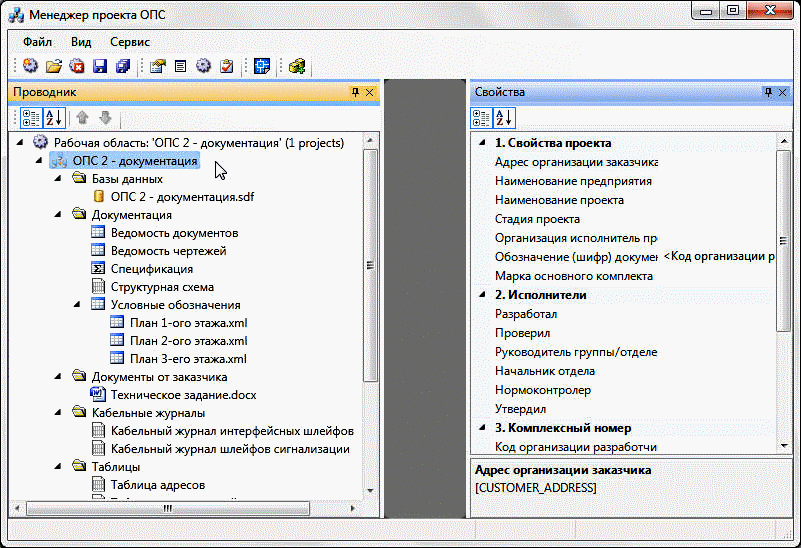
Rice. 1.Project manager
The program allows you to download the vector architectural and construction basis of the construction plan. *.dwg files created in AutoCAD or any applications for it, as well as in other programs that support this format are supported. The program contains databases that are open for editing by users. The program shell implements a separate concept of “Manufacturer Database” and “Project Database” with easy loading of databases of new manufacturers. Information is quickly exchanged between the manufacturer databases and the project database.

Rice. 2. Database manager
The software product provides the following features:
The program allows you to automatically place fire detectors in rooms, taking into account various installation conditions and room parameters.
Some ways automatic installation fire detectors:
The program also allows you to place security detectors and video cameras by specifying the installation angle of the equipment directly when installed on the floor plan of the building.
The program allows you to carry out an assessment calculation of the cable for alarm loops. To carry out an evaluation calculation, it is enough to arrange the equipment and include it in the loops. Next, the program itself will calculate the length of the cable, taking into account the coordinates of the installation of the equipment, as well as taking into account the installation heights of the connected equipment.
If it is necessary to carry out an evaluation calculation of the cable for multi-story building, then it is enough to install UGO of interfloor passages and combine them into a single riser. In this case, the program will calculate the cable taking into account the transition from floor to floor at the given elevation of the floor plan.
After the evaluation calculation, downloading of reporting documents will be available: block diagram, cable logs with calculation results, tabular documents.
One of the features of the program is working with alarm loops. The program provides for working with three types of loops: traditional (non-addressable), addressable, information line (in version 1.0 there was an addressable analog loop). Each loop has its own individual settings, allowing you to bring the designed object as close as possible to its operating conditions.
Only non-addressable detectors will be connected to the non-addressable loop.
Only addressable detectors will be connected to the addressable loop.
Addressable and addressable analogue detectors and other addressable devices will be connected to the information line. It is also possible to set different address ranges for detectors and addressable devices for the information line.

Rice. 3. Properties of loops
The program allows you to automatically route cables along alarm loops. Tracing occurs through cable channels, taking into account the sequence in which detectors are included in the loop. For use in cable signaling loop various types work with distribution boxes is provided.
All connections in the project are made using a single electrical model, which allows you to quickly and accurately create connections for both alarm loops and interface loops.

Rice. 4. Electrical engineering model of the project
In the electrical model, all properties of objects involved in connections are available for viewing and editing. General electrical model cable system is formed:
A 3D view of the floor plan can also be used as a reporting document. The 3D view is created based on the arranged equipment and laid cable channels, as well as the presence of a height parameter in each object installed on the floor plan.
When creating a 3D view, each element is placed on its own layer, which allows you to adjust the visibility of objects in *dwg files. For example, if fire alarm and video surveillance equipment are placed on the same plan, then these systems can be displayed separately on different sheets.

Rice. 5. 3D view of fire alarm
The created 3D views can be used as a means of additional control of the correct installation of equipment on the floor plan.
The program allows you to automatically generate a structural diagram of both the project as a whole and with the possibility of splitting it into systems.

Rice. 6. Block diagram of a security alarm
With the help of configurations, the block diagram can be customized to suit various conditions project implementation. Configurable parameters of the block diagram include:
The program provides the creation of several types of reports, including:
Uploading of tabular reports and specifications is carried out in CAD, as well as in MS Office (Word and Excel) or OpenOffice.org (Writer and Calc).
Using the unique properties of each project, it is possible to upload reporting documents and a structural diagram with a completed title block.
Preparation of drawings for printing is carried out in the AutoCAD Print Manager. MS Excel and MS Word documents included in the project are prepared for printing by MS Excel and MS Word print managers, respectively.

Rice. 7. Floor plan of the building with equipment
Estimated- a free, fully functional temporary license of the program designed to get acquainted with functionality without the right of commercial use. The program can be downloaded and installed only once during a version. It has a validity period of 30 days and requires prior registration on the website, obtaining a serial number and electronic certificate.a commercial– paid full-featured license with the right to commercial use for a period of 1 year. Purchasing a license requires prior registration on the website to receive a serial number and an electronic certificate. It is possible to print a license certificate confirming the legality of using the program.
Educational– free full-featured license without the right to commercial use for a period of 1 year. Purchasing a license requires registration on the website as educational institution and confirmation of status, with receipt of a serial number and electronic certificate. It is possible to print a license certificate confirming the legality of using the program.
Demonstration– a free perpetual license of the program, designed to familiarize you with the basic functionality without the right to commercial use. It has a number of functional limitations and does not require prior registration on the website, obtaining a serial number or an electronic certificate.
The abbreviation OPS stands for compulsory pension insurance and refers to the pension system. Compulsory pension insurance is a state pension program that began operating in the Russian Federation in 2002, after the pension reform in the compulsory pension system. Explanation in the Pension Fund (non-budgetary fund) is given as a system of functioning of participants (insurers, policyholder and insured persons) within the framework of the state program for the formation of funded pensions for all citizens of working age, on whose account payments are made insurance premiums.
Since 2002, fundamental changes have occurred in the Russian pension system. The distribution system was replaced by the distribution-storage system. Thus, since 2002, all citizens born in 1967 and started younger an accumulative pension capital is formed, which amounts to 6% of monthly official earnings, can be managed by the owner and inherited by his legal successors. You can receive the right to pay a funded pension only when the pension grounds arise.
The compulsory pension insurance system includes the following participants:
The OPS agreement stands for compulsory pension insurance agreement. It is a legal document between the insurer and the insured person, as a result of which one party transfers his funded pension to the control of the other party. This agreement is evidence that a citizen, a participant in the OPS system, becomes a client of a non-state pension fund (NPF).
Who has the right to enter into an OPS agreement?
All citizens who are officially employed in the territory of the Russian Federation, on account of which insurance premiums are made, are of legal age (younger than 1966), have the right to sign a compulsory insurance agreement with any non-state pension fund that is included in the DIA register.
After concluding a compulsory security agreement (sometimes also called a compulsory security certificate), the Pension Fund transfers all accumulated funds to the management of the non-state pension fund chosen by the person. In this case, the non-state pension fund assumes the right to invest the pension savings of its client and subsequently bring him income from investment activities. Only those non-state pension funds that have passed the inspection of the Central Bank and are included in the system of guaranteeing the rights of insured persons can invest in the compulsory pension insurance system. According to the new legislative conditions, all pension funds are joint stock companies and can invest pension funds only in those financial instruments that are strictly regulated by law.
LLC "Accent SB"
Accent SB has been using the nanoCAD and nanoCAD OPS platforms for about 4 years. During this time, more than 120 large projects were completed that successfully passed state and non-state examinations. This is largely thanks to these software products.
We thank the support service of Nanosoft JSC for the enormous and prompt work.
JSC "St. Petersburg Marine Engineering Bureau "Malachite"
Since 2014, the bureau has been using nanoCAD software from the Russian developer JSC Nanosoft (Moscow).
The platform has proven itself as effective tool for the creation and release of design documentation. It is important that user suggestions and comments are not ignored, but are taken into account in the development of new versions.
FKP "Privolzhsky State Ammunition Test Site"
In 2013, our company was faced with the question of choosing software to solve design problems. With the support of SeaSoft Samara LLC, an analysis of the available solutions on the CAD market was carried out, and the most optimal solution was selected - nanoCAD software. During the operation of nanoCAD, specialists identified the following positive features like ease of use, constant...
In 2013, our company was faced with the question of choosing software to solve design problems. With the support of SeaSoft Samara LLC, an analysis of the available solutions on the CAD market was carried out, and the most optimal solution was selected - nanoCAD software. During the operation of nanoCAD, specialists have identified such positive features as ease of use, constant improvement of software, and a wide range of products.
LLC "TBSS"
Our designers mastered nanoCAD OPS without any problems, this was made possible by a familiar interface (menus, panels, command line and...
TBSS LLC expresses gratitude to the developers of nanoCAD OPS. Purchasing this program was truly a good price-quality ratio! nanoCAD OPS functionality contains everything necessary tools basic design drawings.
Our designers mastered nanoCAD OPS without any problems, this was made possible by a familiar interface (menus, panels, command line, etc.). The possibility of group automatic error correction significantly saves time.
I would also like to note the fast switching from 2D to 3D with a large amount of data. In automated mode, we generate reporting documents in accordance with domestic standards and upload them to external systems Microsoft Office.
Our company recommends that all designers in the country switch to the domestic CAD system nanoCAD.
LLC "Energospetsproekt"
NanoCAD OPS combines a convenient, specially designed interface, precisely selected and customized graphic display tools, and the ability to perform necessary calculations when selecting equipment. I’m also pleased to be able to work with NanoCAD software on a business trip and at home using a USB dongle.
The menu of the Rubezh-OPS program is quite large and rich in functionality / Each button is responsible for its own functionality
Project setup
You can start a project either on a new blank sheet or on an already existing drawing with a building plan.
It is very important at the first stage to CORRECTLY set the scale of the layout of the building you are working with.

If you have a complete building layout at the time of starting the project, then it is advisable to define the project areas.You can select any logical unit of a building as a separate area, for example, a floor, a building, a section, or an entire building.

A node in a project is a part of a building plan that needs to be drawn out separately, most often on an enlarged scale. The node in the project is set in the project settings window. The scale of the plan within the node is chosen by the user; the main thing is to understand that this is an enlargement relative to the rest of the building plan.


In order to view the equipment included in the Rubezh database, click on the “Rubezh Database” button.

You will see a list of available equipment types. Navigation is carried out along the equipment tree on the left or by icons in the preview window on the right.Before inserting almost any unit of UGO equipment, it is necessary to set the installation height of the equipment from the floor and the ceiling height in meters. This is necessary to automatically calculate the cable length in the project. The installation height of the equipment cannot be greater than the ceiling height. Finally, click the “Insert” button.

For the Reception and Control Equipment, the program automatically assigns a position designation with the required serial number. Sequence numbers cannot be repeated.

When inserting addressable equipment, serial numbers are not immediately entered, since they depend on the number of the Addressable loop that will be connected. Therefore, addressable equipment is inserted with anonymous designations, for example:

After connecting the addressable equipment with a loop, each detector and other addressable equipment receives its own serial position number automatically.

Radio Equipment Insertion
Radio equipment includes only three products - MRK-30 is main device, which is inserted into the addressable loop and immediately occupies 31 serial numbers and two types of detectors (radio smoke and manual), which are connected to the MRK-30.Thus, MRK-30 is the main device, without whose insertion it is impossible to insert dependent detectors.

Risers are inserted from the Rubezh equipment database. A total of 10 types of risers are offered. When inserting a riser, you need to specify its length; in fact, this is the height of the wall from floor to ceiling, that is, the distance that the riser occupies.

Let's give an example of inserting risers and setting their length. Each project may have its own options for inserting risers.

Cables
There are several types of cables in this program, each type of cable has its own restrictions on length and other parameters.
Address cable– the position designation (marking) is rigidly specified – ALSx.y, where x is the number of the control panel and y is the serial number of the ALS extending from this control panel. Numbers X and Y are entered automatically when specifying the Control and Receiving Device from which the ALS departs. Most often, 1, 2, 4 address cables can extend from one control panel.
The address cable has a length limit of 1000 meters. The program issues the first warning when the cable reaches a length of 900 m; after exceeding the length of 1000 meters, the program does not allow drawing of the cable.
Interface cable- position designation (marking) is set rigidly – RSх, where x is the serial number of the cable RS is assigned automatically by the program.
The interface cable has a length limit of 1000 meters. The program issues the first warning when the cable reaches a length of 900 m; after exceeding the length of 1000 meters, the program does not allow drawing of the cable.
Other cables– any type of cable other than the Address cable (loop) and interface cable. Any positional designation (marking) can be specified. Only the presence of duplicate markings is checked.
To start drawing a cable, you need to click the “Draw cable line” button. A cable line can contain one cable or a group of cables, that is, you can draw Routes.Before you start drawing a cable that is not in the project, you must first add it to the Project.

When you have one or more required cables in your project, you can start drawing them. You can add one or more cables from a project to a cable line. Each time you can choose how many cables to draw - one or several. Use the checkboxes to select the required cables. Next, click the “Draw cable line” button.

The program checks the cable to see if it can be connected to a given device. For example, the RS interface cable cannot be connected to a fire detector. In this case, the program issues a warning “Inappropriate block”:

After the cable line is drawn, the length of the drawn cables is shown in the “Draw Cable Line” window. The cable length is calculated depending on the scale specified in the Project Settings.

Leaders are placed by clicking the “Mark cable line” button. You need to click the button and then select the cable lines over which you want to place callouts. A leader can be placed several times on one cable line. If several cables are drawn in one line in the drawing, the program displays a multileader with the names of all cables.

The program implements very handy tool– Manager of standard floors. This tool allows you to virtually replicate one typical floor. That is, a typical floor will not have to be drawn several times. The program itself will count the number of equipment, create all positional designations, and automatically lay cables along all typical floors taking into account their length.

Release of documentation
Documentation can be released at any time. Clicking the Documentation button first starts checking the project for errors.

Select the areas for which you want to display documentation. If you do not have areas, you can display documentation for the entire project or define areas in the Documentation window. If you want to split the Document by project areas, then check the “Split by project areas” checkbox.

By analogy, you can publish a cable magazine.

This type of document displays a list of addressable equipment for all ALS or for ALS separately.
 .
.
In essence, this is a legend of the UGO (symbolic graphical symbols) on the drawing indicating the quantity st va blocks of the same type in the drawing.

Typical schemes
Typical equipment diagrams are placed on the drawing automatically as optimally as possible. There may be cases where the diagrams go beyond the frames, then the diagrams need to be moved a little manually.


