The owners of the patent RU 2342759:
Usage: for reactive power compensation. The technical result consists in simplifying the method and eliminating the reverse effects on the operating voltage. The reactive power compensator contains several compensation components located parallel to each other (K1-K3). To connect the reactive power compensator to the operating voltage (U), first the compensation components (K1-K3) are connected in series with the control unit (CU) to the operating voltage (U) via an additional resistance (R). Only then are the compensating components (K1-K3) connected to the operating voltage (U) free of additional resistance. 4 n. and 16 z.p. f-ly, 6 ill.
The present invention relates to a method for connecting to an operating voltage for a reactive power compensator with several compensating components arranged in parallel to each other according to paragraph 1 of the claims.
It further relates to the control program stored on the data carrier, the control unit for the reactive power compensator and the reactive power compensator, which are configured to implement such a connection method.
VAR compensators - so-called SVC systems (SVC=static VAR compensator) - usually contain a thyristor-controlled reactance TCR (TCR=thyristor controlled reactance) and at least one filter circuit. They are used in energy-intensive consumers that are supplied with alternating current from an alternating voltage network and serve to compensate for reactive power components. alternating current.
The reactive power compensator is usually connected to the AC voltage network (or, in general, to the operating voltage) and also disconnected from it again. When connecting a reactive power compensator, crosstalk can occur in the operating voltage and/or in the current currents. In an extreme case, this can lead to the fact that another installation, which is also supplied with the operating voltage, is switched off in an emergency. The consequence is production failures or other operational damage.
In order to avoid such operational damage, the reactive power compensator in the prior art is connected to the operating voltage only when other installations or parts of installations that are also supplied with operating voltage, the trouble-free operation of which must be ensured, are not in operation. This limits, however, not only the efficiency when connecting the reactive power compensator to the operating voltage. Moreover, this course of action can only be achieved in practice at great expense.
Further, it is known that in multi-phase AC networks, the individual phases of the AC network are connected to the reactive power compensator one after the other with a certain time offset relative to the voltage zero crossing of the corresponding phase. However, this requires special, expensive switching devices.
The object of the present invention is to provide a connection method for a reactive power compensator that avoids unacceptably high reverse effects on the operating voltage and that can be implemented more simply than the above-mentioned connection method of the prior art.
The problem for the connection method, whereby the compensating components are connected to the operating voltage by the control unit one after the other, first via a series resistor and then without a series resistor, is solved by using an active component from to at least one controlled reactive power element, for example with TCR (thyristor controlled reactance).
For the control program, the control unit and the reactive power compensator, the problem is solved by the fact that they are made with the possibility of implementing the connection method according to the invention.
Since due to this, not the entire reactive power compensator is connected immediately to the operating voltage. Moreover, there is a time-stepped and, due to additional resistance, damped connection of the compensating components to the operating voltage. Only when this connection is completed is the reactive power compensator connected to the operating voltage without additional resistance.
Due to the fact that, according to the invention, the compensating component, firstly connected to the operating voltage via a series resistor, is an active component with at least one controllable reactive power element, for example containing a TCR (thyristor-controlled reactance), active control is possible from the very beginning current flowing through the additional resistance. This, in particular, can be used to basically compensate for the current of the fundamental frequency of the alternating voltage flowing through the additional resistance.
The compensation circuits connected after the first compensating component to the operating voltage via a series resistor are, as a rule, purely passive filter circuits.
If the series resistor is disconnected from the operating voltage by the control unit after the compensating components are connected to the operating voltage free from the series resistor, then any continuous current flow through the series resistor is excluded. This is an advantage, in particular, because then, if the reactive power compensator is later disconnected from the operating voltage, this disconnection can take place without taking into account the additional resistance.
If the connection of the compensating components to the operating voltage without additional resistance is carried out simultaneously for all compensation components, then the connection without additional resistance can be implemented particularly simply.
The connection method according to the invention works particularly well if the time offset between the connection of two compensating components connected directly one after the other to the operating voltage via a series resistor lies between 50 and 300 ms. Because a good compromise is then possible between connecting the entire reactive power compensator with low backlash and quickly being able to react to an event that requires the connection of a reactive power compensator. The time offset in this case should preferably lie between 80 and 200 ms, for example between 100 and 150 ms.
In order to implement the connection method according to the invention, it is possible, for example, to connect the compensating components to the operating voltage by connecting a distribution bar located upstream of the compensating components to the operating voltage via a series resistor and connecting the compensating components to the distribution bar. In this case, in particular, it is possible, in particular, for the subsequent resistance-free connection of compensating components to the operating voltage, to connect the distribution busbar free of additional resistance to the operating voltage.
Preferably, the first compensation component is connected to the distribution bar only after a time delay after being connected to the operating voltage of the distribution bar via a series resistor.
The time delay can have the same values as the time offset.
A common application is that the operating voltage is high voltage, in particular a medium voltage between 6 and 36 kV.
If the operating voltage has several phases and the phases are connected to the compensating components at the same time by the control unit, then the connection method according to the invention can be implemented particularly simply.
Further advantages and details follow from the following description of the exemplary embodiment in connection with the drawings. At the same time, in principle, they show:
Fig.1 - block diagram of the reactive power compensator,
Fig.2 - timing diagram,
Fig.3 - voltage timing diagram,
Fig.4 - timing diagram of the current,
Fig.5 - timing diagram of voltage and
Fig.6 - timing chart of the current.
According to Figure 1, the reactive power compensator contains several compensating components K1 to K3. Compensation components K1 to K3 are arranged parallel to each other with respect to the distribution bar DL. According to Figure 1 there are three compensation components K1 to K3. However, there may also be more or less compensation components K1 to K3. The quantity must not, however, decrease from less than two compensation components K1 to K3.
Compensation component K1 is an active component with at least one controllable reactive power element. The controlled element of reactive power in this case is made according to Fig. 1 in the form of a TCR (thyristor-controlled reactance). It thus contains a thyristor unit T, by means of which the reactance of the compensating component K1 is controlled. According to FIG. 1, the compensation component K1 additionally also contains a purely passive filter circuit. This, however, is not necessarily necessary. The other compensation components K2 and K3 are purely passive filter circuits.
Compensation components K1 to K3 can be connected via a switch S1 to S5 and a series resistor R to the operating voltage U. The operating voltage U is usually a high voltage, for example a medium voltage between 6 and 36 kV. It is usually an AC system with three phases. In a particular case, it may also be an AC system with more than three phases, for example an AC system with four or five phases. It can, however, also be a single-phase voltage system.
The reactive power compensator further comprises a control unit CU which controls the switches S1 to S5 and the thyristor unit T. The control unit CU is in this case a programmable control unit CU which executes the control program CP. In this case, the control program CP is supplied to the control unit CU via a data carrier DC, on which the control program CP is stored in a (exclusively) machine-readable form.
Based on the programming by the control program CP, the control unit CU connects the compensation components K1 to K3 of the reactive power compensator to the operating voltage U in the following manner, explained in more detail in connection with FIG. 2.
If the ON command is applied to the control unit CU, the control unit CU first closes switch S1 immediately. In this way, the distribution bar DL is first connected to the operating voltage U.
It is also possible to close switch S2 at the same time. If necessary, switch S2 can even be omitted. According to FIG. 2, the control unit CU closes switch S2, but only after a time delay δt1. After the time offset δt2 has expired, the control unit CU then closes the switches S3 and S4. Thus, all compensating components K1 to K3 are connected to the operating voltage U via a series resistor R.
After the time offset δt2 has elapsed again, the CU control unit closes switch S5. After closing switch S5, the control unit CU waits again for the time offset δt2 and then opens switch S1.
The time delay 5t1 is preferably between 50 and 300 ms, in particular between 80 and 200 ms. According to Figure 2, it lies, for example, at 100 to 150 ms. The time offset δt2 is preferably between 50 and 300 ms, in particular between 80 and 200 ms. According to FIG. 2, it lies, for example, at 100 to 150 ms. The time delay δt1 and the time offset δt2 in particular can have the same value.
As can be seen from Fig.3, for one of the phases of the operating voltage U, the operating voltage U has a fundamental frequency f. The control unit CU according to FIG. 1 controls not only the switches S1 to S5, but also the thyristor unit T. The thyristor unit T and thus the active component K1 are controlled by the control unit CU in such a way that the current I flowing through the series resistor R is mostly canceled because it has a fundamental frequency f. The thyristor unit T is thus controlled depending on the control commands issued to the switches S1 to S5. This is clearly seen from Fig.4.
By means of the connection method according to the invention, significantly lower network repercussions are achievable than with conventional connection methods according to the state of the art. This is true even though, in the solution according to the invention, all phases are switched on by switches S1 to S5 at the same time. The advantages of the connection method according to the invention compared to the conventional connection methods according to the prior art are shown in particular by comparing FIG. 3 with FIG. 5 and comparing FIG. 4 with FIG. Since FIGS. 5 and 6 show the current waveform and the voltage waveform that appear when the usual way connections according to the state of the art. It can be seen that with the conventional method according to the state of the art, considerably greater feedback effects on the network occur than in the connection method according to the invention.
1. Connection method for a reactive power compensator with several compensation components (K1-K3) arranged in parallel to each other to the operating voltage (U), wherein the compensation components (K1-K3) are connected to the operating voltage (U) by the control unit (CU) first one after the other through an additional resistance (R) and then without an additional resistance, characterized in that an active component (K1) with at least one controlled reactive power element, for example, thyristor controlled reactance (TCR).
2. Connection method according to claim 1, characterized in that the operating voltage (U) is an alternating voltage with a fundamental frequency (f) and that the active component (K1) is controlled by the control unit (CU) in such a way that the current through the additional resistance (R ) the current (I) of the fundamental frequency (f) is essentially compensated.
3. The connection method according to claim 1, characterized in that the compensation components (K2, K3) connected after the first compensation component (K1) through an additional resistance (R) to the operating voltage (U) are filter circuits (K2, K3).
4. The connection method according to claim 2, characterized in that the compensation components (K2, K3) connected after the first compensation component (K1) through an additional resistance (R) to the operating voltage (U) are filter circuits (K2, K3).
5. The connection method according to claim 1, characterized in that the additional resistance (R) is disconnected by the control unit (CU) from the operating voltage (U) after the compensation components (K1-K3) are connected to the operating voltage (U) free from additional resistance.
6. The connection method according to claim 2, characterized in that the additional resistance (R) is disconnected by the control unit (CU) from the operating voltage (U) after the compensation components (K1-K3) are connected to the operating voltage (U) free from additional resistance.
7. Connection method according to claim 3, characterized in that the additional resistance (R) is disconnected by the control unit (CU) from the operating voltage (U) after the compensation components (K1-K3) are connected to the operating voltage (U) free from additional resistance.
8. Connection method according to claim 4, characterized in that the additional resistance (R) is disconnected by the control unit (CU) from the operating voltage (U) after the compensation components (K1-K3) are connected to the operating voltage (U) free from additional resistance.
9. The connection method according to any one of claims 1-8, characterized in that the connection of compensation components (K1-K3) to the operating voltage (U) free from additional resistance is carried out simultaneously for all compensation components (K1-KZ).
10. Connection method according to any one of claims 1 to 8, characterized in that the time offset (δt2) between the connection of two compensation components (K1-K3) connected directly one behind the other via an additional resistance (R) to the operating voltage (U) lies between 50 and 300 ms, in particular between 80 and 200 ms, for example at 100 to 150 ms.
11. Connection method according to any one of claims 1-8, characterized in that to connect to the operating voltage (U) through the additional resistance (R) compensation components (K1-K3) to the operating voltage (U) connect the distribution bus (DL) located in front of the compensating components (K1-K3) and connect the compensating components (K1-K3) to the distribution busbar (DL).
12. The connection method according to claim 11, characterized in that for connection free from additional resistance (R) to the operating voltage (U) of compensating components (K1-K3), to the operating voltage (U) is connected free from additional resistance (R) distribution bus (DL).
13. The connection method according to claim 12, characterized in that the connection of the first compensation component (K1) to the distribution bus (DL) is carried out only after a time delay (δt1) after the distribution bus (DL) is connected to the operating voltage (U) through an additional resistance (R).
14. Connection method according to claim 13, characterized in that the time delay (δt1) lies between 50 and 300 ms, in particular between 80 and 200 ms, for example at 100 to 150 ms.
15. Connection method according to claim 14, characterized in that the time delay (δt1) is equal to the time offset (δt2).
16. Connection method according to claim 15, characterized in that the operating voltage (U) is a high voltage, in particular a medium voltage between 6 and 36 kV.
17. Connection method according to claim 16, characterized in that the operating voltage (U) is applied with several phases and that the phases are connected to the compensating components (K1-K3) by the control unit (CU) at the same time.
18. A computer-readable storage medium (DC) containing a control program stored thereon, the execution of which by a programmable control unit ensures the implementation of the connection method according to any one of claims 1-17.
19. A control unit for controlling a reactive power compensator, with a machine-readable control program, upon execution of which the control unit ensures the implementation of the connection method according to any one of claims 1-17.
20. A reactive power compensator with several compensation components, with a control unit according to claim 19, with which the compensation components can be controlled in accordance with the connection method according to any one of claims 1 to 17.
Similar patents:
The invention relates to the field of electrical engineering, in particular to high-voltage regulated electrical complexes, and can be used in high-voltage electrical networks with a voltage of 110...750 kV for reactive power compensation and voltage stabilization.
ZAO "Energoprodukt"
Address: 614000 5, office 402
Tel: (342); ; ;
E-mail: uranium @ perm. raid. ru Website: http :// www. energy product. en
Perm 2012
1. Introduction
2. Appointment
3. Technical data
4. Maintenance
5. Composition of the product
6. Design and operation of the product
7. Marking. Conservation. Package
8. Connection procedure
9. Preparation for work
10. How to work
12. Security measures
14. . Resources, service life, storage, manufacturer's warranties
1. Introduction
All consumers of electricity, whose work in the nominal mode represents the process of creating alternating magnetic fields, consume from the network electrical power having active and reactive components.
The reactive component or reactive power is necessary for the operation of the equipment and at the same time is an undesirable additional load on the network; therefore, it is advisable to generate reactive power directly at the consumer. One way to solve the problem is to use reactive power compensation units.
This operating manual is intended for studying reactive power compensators of the KRM-0.4 series and the rules for its operation.
This document contains specifications reactive power compensators and the conditions for their use, information about the device and the principle of operation, instructions for safety measures, rules for installation, preparation for operation and maintenance, as well as information on preservation, transportation and storage.
2. Appointment
Adjustable reactive power compensation units KRM-0.4 are designed to maintain a constant set value of the power factor (cos) in electrical distribution three-phase networks of industrial enterprises and other facilities with voltage up to 400 V, frequency 50 Hz.
3. Technical data
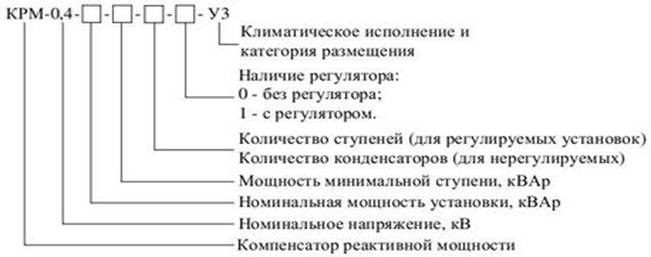
KRM - capacitor unit with automatic reactive power control.
Parameter name | Meaning |
Rated voltage, V | 400 |
Maximum operating voltage, V | 660 |
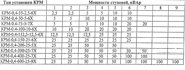
Rated power, kvar | 20-300 |
Number of power control steps (For adjustable installations) | 4-12 |
Step power, kvar | 5-60 |
Supported cos value in automatic mode | 0,8-1 |
Rated voltage Auxiliary circuits, V | 220 |
Degree of protection according to GOST | U3 |
4. Maintenance
KRM-0.4 units can operate in automatic or manual control mode. The choice of the control mode is carried out by the button located on the front panel of the regulator.
In the automatic control mode, when the value of reactive power changes, the regulator switches on and off the stages of the installation with a time delay in the range s.
In the manual control mode, the stages are switched on and off with a time delay (programmed by the operating personnel).
With manual control of the installation, the required number of stages included is determined by the readings of the regulator. It is forbidden to re-switch on the steps of the installation earlier than after 5 minutes. After shutdown to avoid the failure of the capacitors.
When operating in the automatic control mode, the capacitors are switched on and off automatically, depending on the deviation of the network control parameter beyond the limits of the selected setpoints.
The switching logic is carried out directly by the reactive power controller itself.
Power. In case of blown fuses in power and secondary circuits the installation can be restarted only after the reasons for the shutdown have been clarified and eliminated.
Maintenance of the installation is carried out once a month. The scope of work during maintenance includes an external inspection, cleaning the installation from dust and checking the quality of the clamping of screw contact connections.
Excluded:
Continuous operation of installations with a voltage on the busbars of more than 1.1 UNOM,
it should be borne in mind that when the capacitors are turned on, the voltage in the network rises;
Re-enable KRM-0.4 after the regulator protection is triggered due to overcurrent of capacitors until the reasons for the overload are clarified;
Re-enabling the units earlier than 5 minutes. after shutdown;
Carrying out operations with a knife switch when the starters are on.
Structure symbol KRM-0.4
The KRM-0.4 units provide the specified cos during periods of maximum minimum loads, and also exclude the reactive power generation mode.
5. Composition of the product
Standard delivery set of the installation:
product name | Designation | Qty |
Condensing unit KRM-0.4 | ||
Condensing unit KRM-0.4 Passport and instruction manual | ||
Reactive power regulator. User manual |
6. Device and product operation
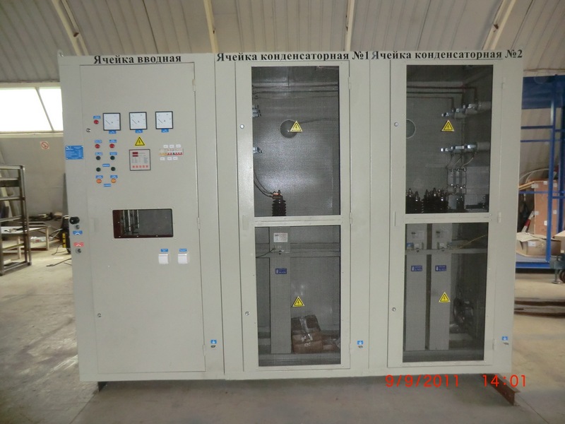
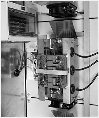
The installation consists of capacitors, which are switched by specialized contactors. Control commands come from a microprocessor-based reactive power controller (hereinafter referred to as the "regulator"). All components in a metal cabinet.
A capacitor (one or more connected in parallel) equipped with external discharge resistors, a dedicated contactor and fuse links forms the capacitor section. To increase the power of the capacitor stage, the capacitor sections can be connected to control contactors. In the simplest case, each stage consists of one capacitor section. Capacitors work in standard version with natural cooling. If necessary, a ventilation system is installed to improve cooling.
The installation has a zero terminal intended for connection of a neutral conductor. The maximum cross section of the connected conductor is 2.5 mm. It is also possible to install a zero bus that allows you to connect a zero working conductor with a cross section of more than 2.5 mm (optional). There are also holes for connecting the installation cabinet to the grounding bus and to portable grounding. Zero and earth are marked accordingly.
The regulator provides the possibility of automatic or manual regulation of reactive power. Regulation is based on measuring the current and voltage of the network. Therefore, the regulator must be connected to an external (measuring) current transformer.
Switching on and off of sections is carried out by specialized KM electromechanical contactors. The section enable/disable delay can be adjusted by the user.
After being disconnected from the mains, each capacitor section is discharged by means of discharge resistors.
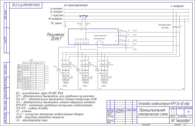
An electrical circuit diagram with a specification of the installation components is given.
ATTENTION: KRM-0.4 is connected with a cable with copper conductors with a cross section designed for rated current, taking into account the type of cable and the conditions for its laying.
ATTENTION: When using KRM in a network with shared neutral N (zero) and ground PE - connect a jumper from the wire (if not available) to the blue terminal marked with neutral N on terminal block with yellow-green terminal PE . When using KRM in a network with separate neutral N (zero) ground PE N (neutral) on the terminal block with yellow-green terminal PE.
The KRM-0.4 units provide the specified cos during periods of maximum-minimum loads, and also exclude the mode of reactive power generation.
The use of KRM-0.4 allows:
Maintain the required power factor of consumer installations;
Improve the quality of electricity directly in the networks of enterprises;
Reduce overall energy costs;
Reduce the load on the distribution network elements, increase their service life.
7. Marking. Conservation. Package
KRM-0.4 units have a plate indicating:
Name of the country of manufacture (Russia);
Name of the manufacturer's enterprise;
Symbol KRM;
Serial number according to the numbering system of the manufacturer;
date of manufacture;
Rated voltage in volts;
Mass in kilograms;
Method of marking according to the manufacturer's technology.
All external contact surfaces that do not have anti-corrosion coatings are protected from corrosion during transportation with a preservative lubricant or its analogues.
Types of packaging and methods of preservation of KRM-0.4 units according to GOST 23216 for a group of products.
During transportation, all moving parts of the cabinets must be secured before packing.
Cable entries must be closed with plugs that protect against the ingress of water and dust during transportation and storage.
Operational, accompanying documentation for KRM-0.4 cabinets must be packed in accordance with GOST 23216.
8. Connection procedure
Before connecting, make sure that there are no mechanical damages.
installations, foreign objects, dust and dirt.
Measure the electrical resistance between current-carrying
connected and grounded parts electrical circuits voltage megger
1000 V. It must be at least 1 M Ohm.
Place the unit in a non-flammable and non-explosive room
directly on the floor in places where there is no possibility of its mechanical
damage, not subject to sharp shocks and shocks, as well as vibration effects
with a frequency above 50 Hz and a maximum acceleration of more than 0.5 g.
Fix the installation cabinet to the foundation or to the wall of the room and connect it to the local ground loop.
Check the quality of the clamp and, if necessary, tighten the screw contact connections(clamp may loosen during transport).
Connecting the unit to the network.
The cross section of the conductors connecting the unit to the network must correspond to the rated current, cable type and laying conditions.
When connecting the unit through fusible links, their rated current must be at least 1.3x I nom.
When using KRM in a network with a combined neutral N (zero) and ground PE – connect the wire jumper (if not available) to the blue terminal with the marking N (Neutral) on the terminal block with green/yellow terminal PE . When using KRM in a network with separate neutral N (zero) and ground PE - remove the jumper from the wire (if any) between the blue terminal with the marking N (neutral) on the terminal block and yellow-green terminal PE.
It is necessary to connect the neutral working conductor to the terminal block. It must be borne in mind that the connection to the neutral working conductor is needed only for measuring network parameters by the installation and powering the regulator and contactors, therefore its cross section is not less than 0.75 mm and not more than 2.5 mm in the standard version of the installation. It is possible to organize the connection of a neutral conductor of large cross section to a special bus terminal (optional).
When connecting phase conductors to the installation, they must be connected to the corresponding phases of the installation.
Connecting a current transformer.
The current of the primary winding of the current transformer must be designed for the rated current of the network, the current of the secondary winding can be 1A or 5A.
ATTENTION! Common mistake lies in the fact that the current transformer is selected based on rated current setup, which is wrong.
The current transformer is connected to the phase L 1 between the power source and the connection point of the KRM according to the above diagram.
Insert the KRM into the housing and connect, in accordance with the electrical circuit diagram, the wires coming from the current transformer. It must be borne in mind that the terminal block for connecting the CT is designed for wires with a maximum cross section of not more than 25 mm.
9. Preparation for work
To prepare the installation for operation, it is necessary, in accordance with the relevant section of the regulator's operating manual, to set its operation mode based on the requirements for achieving optimal technical and economic characteristics of regulation, taking into account the characteristics of the installation.
When choosing delays, be guided by information about the inertia of processes in the load. In order to increase the resource of switching equipment, it is necessary to exclude short-term switching on and off of the stages during random, short-term changes in the load. We recommend that you do not change the default values without a good reason.
Check the operation of the installation in automatic mode.
If necessary, check operation in manual mode.
10. Order of work.
Recommended in initial period operation, as well as in case of seasonal temperature changes (when installed in a poorly heated room), monitor the operation of the unit. sign of normal operation and correct installation The governing bodies of the regulator are:
Presence of display indication - if there is no indication, replace the fuse located in the terminal block;
No overcompensation.
At a mains voltage of 420-440 V, the operation of the unit is not allowed for more than 8 hours, at a voltage above 440 V - no more than 1 minute.
11. Typical malfunctions
Typical malfunctions and methods for their elimination are given in the table:
Malfunction manifestation | Elimination Method |
1. Regulator indicator not lit | Replace fuse (in terminal block) |
2. After connecting the regulator does not compensate for the reactive power in the network | Eliminate errors in the connection of the regulator |
3. When the capacitors are switched on, the power factor of the network decreases | Eliminate errors in the connection of the CT: swap the leads |
4. Contactors won't turn on | Repair an open circuit in the control circuit of the contactor coils |
12. Security measures
KRM-0.4 has protection against short-circuit currents, acting on shutdown without time delay.
The protection must be tuned out from the switching currents of the installation and current surges in case of overvoltages.
The KRM-0.4 installation has protection against overvoltage, which turns off the battery when the effective voltage value rises above the permissible value. Switching off the installation should be carried out with a time delay of 3-5 minutes. Re-enabling the capacitor unit is allowed after the voltage in the network drops to the nominal value, but not earlier than after 5 minutes. after turning it off.
In cases where it is possible to overload capacitors with higher harmonic currents
protection is provided that switches off the installation with a time delay when the effective current value for single capacitors exceeds 130% of the nominal value. For installations with two or more parallel branches, protection is also provided, which operates in case of violation of the equality of circuit currents.
Capacitors have fuses, one for each section, which are triggered when the section breaks down.
Scheme electrical connections capacitor banks and fuses are selected so that damage to the insulation of individual capacitors does not lead to the destruction of their cases, an increase in voltage above the long-term allowable voltage on the capacitors remaining in operation, and shutdown of the battery as a whole.
External capacitor fuses have blown indicators. The blown indicators of the external capacitor fuses are available for inspection during battery operation.
The connection of the terminals of the capacitors to each other, their connection to the tires is made by flexible jumpers. Drive handles and control equipment, as well as measuring, metering and signaling devices are located on the front of the cabinets. Plates with inscriptions indicating its purpose are located on the facade of the installation.
The KRM-0.4 units have a protective interlock that ensures that the magnetic starters are turned off when the unit door is opened, while the busbars, fuses and the upper terminals of the starters remain energized.
KRM-0.4 have light-signal indicators indicating the presence of voltage on them, shutdown of units in case of overload and indicators indicating the inclusion of each stage.
On the KRM-0.4 unit, devices are provided for grounding load-bearing metal structures that may be energized during the operation of the unit. A ground bolt is also provided for each capacitor bank.
KRM-0.4, produced according to these specifications, do not create radio interference, as well as noise and vibration harmful to personnel, and they are not subjected to appropriate tests.
13. Transportation and storage rules
Transportation of KRM-0.4 is carried out by all modes of transport in accordance with the "Rules for the carriage of goods" in force for each type of transport.
The conditions of transportation, storage and permissible shelf life before commissioning are established by GOST 15150, GOST 23216.
Transportation of packaged KRM-0.4 units is carried out according to the group of transportation conditions C in accordance with GOST 23216. Storage conditions for KRM-0.4 according to group 7 (Zh1) GOST 15150.
The period of transportation and intermediate storage in case of reloading should not exceed 3 months. Cases KRM-0,4 are transported in packing. During transportation and loading and unloading operations, KRM-0.4 cabinets must not be tilted and subjected to sharp shocks and shocks. For lifting and moving, grab only where there are lifting rings or where the place for catching with a rope is indicated.
Storage of KRM-0.4 cabinets should be carried out in a closed ventilated room in shipping container or without it. Sharp fluctuations in temperature and air humidity in the room where KRM-0.4 cabinets are stored are not allowed. When stored under a canopy, KRM-0.4 cabinets must be in a transport package.
14. Resources, service life, storage,
manufacturer's warranty
The manufacturer guarantees the compliance of KRM-0.4 with the specifications, subject to the conditions of transportation, storage, installation and operation established by the operational documents.
Warranty period of operation is 1 year from the date of putting KRM-0.4 into operation, including the date of shipment from the manufacturer.
Warranty period for the component equipment in accordance with the specified in the standards or specifications for this accessory.
The load of enterprises is divided into active, inductive and capacitive, all these types of capacities depend on the type of operating equipment.
The existence of reactive energy has a negative impact on electrical networks, creates electromagnetic fields in electrical devices.
The existence of a reactive current creates an additional load, leading to a decrease in the quality of electricity, resulting in an increase in the cross sections of the current conductors.
The main purpose of the device is to reduce the action, it serves to increase and maintain at a certain standard level the value of the power factor in three-phase distribution networks. The main purpose of the UKRM is the accumulation of reactive power in capacitors. This action helps to unload the electrical network from reactive power flows, voltage stabilization occurs, and the share of active power increases.
The reactive power compensation unit UKRM has a number of advantages due to the use of capacitors, supplemented by the third level of safety in the form of a polypropylene segmented film impregnated with a special liquid, ensuring reliable use, durability, low cost when performing work on maintenance and repair.
The presence in the capacitor unit UKRM of specialized thyristor high-speed starters operating with a time advance for switching phase capacitors that operate when cosφ changes, extends their uptime.
To ensure the regulation of cosj in automatic mode with the transfer of information to a PC with control in the network of higher harmonics of current and voltage, controllers with contactor switching are used.
To improve the quality of the work of the UKRM, the installation has an odd harmonic filter and a thermoregulation device; an indication system has been thought out to detect faults.
All equipment is placed in a block-container equipped with ventilation and heating with automatic control. The devices provide comfortable and convenient service at low temperatures down to -60 ° C.
The modular type of construction contributes to the gradual increase in the capacity of the UKRM.
For the safe operation of the device, protections are provided:
There are several types of UKRM installations used in 6-10 kV networks, these are:
IN modular installations KRM steps are structurally combined into a module
The most optimal connection of a reactive power compensation device is to install the device in close proximity to the consumer (individual compensation). In this case , the cost of a reactive power compensation installation, consisting of the sum of the cost of implementation and further maintenance, is a significant amount.
When combining loads into a single complex for the consumption of reactive power, it is advisable to apply group compensation. In this case, the use of the price of a reactive power device becomes the most acceptable when put into operation, but less profitable for users due to a decrease in active losses in the electrical network that affect cost savings.
It is possible to connect the KRM device as a separate equipment with an individual cable gland, or as part of a low-voltage switchgear, for example, as part of the main switchboard.
To select the UKRM, the total total power of the capacitor banks of the electrical installation is calculated, according to the formula:
Qc = Px (tg(1)-tg(f2)).
Where P is the active power of the electrical installation
Indications (tg (f1) -tg (f2)) are found according to cos (f1) and cos (f2)
The value of cos(φ1) of the power factor before installing the UKRM
The value of cos(φ2) of the power factor after the installation of the UKRM is set by the power supply company.
The power formula looks like this:
k- tabular coefficient corresponding to the values of the power factor cos (f2)
The power of the UKRM is determined specifically for all sections of the electrical network, depending on the nature of the load and the method of compensation.
Only after a full analysis of the indicators obtained during the diagnostics of the data, it becomes possible to choose regulated or unregulated MCRM.
The degree of power splitting by steps, the time and speed of repeated operation of the steps are indicated, the need to use reactive power compensation in the capacitor installation to reduce the non-sinusoidality factor in the supply network, filter out odd harmonics, and also the absence of the resonance effect is revealed. This ensures power quality.
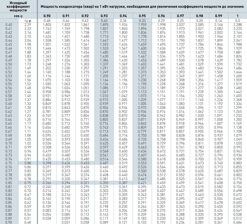
It is necessary to know that it is impossible to make full compensation of reactive power up to unity, this leads to overcompensation, which can occur as a result of a non-constant value of the active power of the consumer, as well as as a result of random factors. The desired value of cosph2 is from 0.90 to 0.95.
APPLIED TECHNOLOGIES:
Personal protection
capacitor stages fuses with fuse links
Protection of capacitor installations
from external influence IP-21; IP-54; IP-55 and above
Climatic performance
At the request of the Customer: U1, U3, UHL1; UHL3; UHL4; HL1
Quality build
Assembly of installation components based on terminals and cable lugs
BENEFITS FOR THE CUSTOMER:
Customized Capacitor Manufacturing
(non-standard control stages, requirements for increased strength of capacitors)
Domestic equipment
Application in installations of domestic components
Fast assembly times
Assembly of capacitor units from 5 working days
The only domestic manufacturer
three-phase capacitors for power factor correction according to European technology

Reactive power - part of the total power spent on electromagnetic processes in a load that has capacitive and inductive components. Does not perform useful work, causes additional heating of conductors and requires the use of an energy source of increased power.
Reactive power refers to technical losses in power networks in accordance with the Order of the Ministry of Industry and Energy of the Russian Federation No. 267 dated 04.10.2005.
Under normal operating conditions, all consumers electrical energy, whose mode is accompanied by the constant occurrence of electromagnetic fields (electric motors, welding equipment, fluorescent lamps, etc.) load the network with both active and reactive components of the total power consumption. This reactive power component (hereinafter referred to as reactive power) is necessary for the operation of equipment containing significant inductances and at the same time can be considered as an undesirable additional load on the network.
For clarity and a better understanding of the ongoing processes, we recommend that you familiarize yourself with the video about reactive power:
Depending on the existing tasks of the client, the best options for solving them can be Various types capacitor units.
So, for example, unregulated capacitor units (UCRM) are the best solution in cases where the reactive power of the compensated circuit element is known for certain, and compensation is carried out on site (individual compensation). The undoubted advantage of this solution, due to its structural simplicity, is its:
Fixed installations are the optimal solution for individual compensation: induction motors, transformers, industrial pumping equipment and air conditioners.
In turn, automatic capacitor units (AUKRM) are the optimal solution for group compensation, in case of a large number of reactive power sources. In this case, individual reactive power compensation may become unprofitable due to the large number of equipment, and the best option is the connection of the installation, which, depending on the level of reactive load in the network, will include the required number of compensation steps. An important advantage of the products of the Nyukon capacitor plant is the presence of fast-discharge resistors in the design of its own capacitors, which improves the quality of compensation not only with a slowly changing load (1 time in 2-3 minutes), but also with an average variable load (1-2 times per minute). ).
If it is necessary to compensate in the network of a sharply variable reactive load, thyristor capacitor units (CRMT) are used.
The main advantages of thyristor capacitor units:
Thyristor-based capacitor units are mainly used at the following facilities:
Thyristor reactive power compensators can be used at facilities where low-noise equipment is required:


