You've probably seen modern TVs with dynamic backlighting called Ambilight, developed by Philips. The essence of her work is to illuminate the space behind the TV with different combinations of colors depending on the events happening on the screen. However, to purchase such a TV you need to shell out several tens of thousands of rubles, so it is not available to everyone.
At the same time, fans of watching movies on a monitor screen and fans of computer games do not need Philips Ambilight TVs.
What should ordinary computer scientists do, who also want to bring into the surrounding space an amazing play of light that magically escapes the boundaries of the monitor? We present to you a new development called PaintPack. This module is designed to implement the same idea as Ambilight technology, but allows you to achieve “light around” any computer monitor, and not a large TV specifically purchased for this purpose.
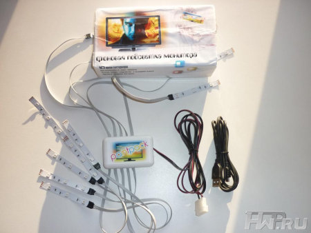
A simpler version of a device called PaintPack is a small box with ten cables with bright LEDs at the ends. These LEDs are placed evenly around the perimeter of the back of the monitor and create uniform illumination in accordance with what is currently happening on the screen. The second, more advanced version of the Russian analogue of Ambilight is the PaintPack light strip with 30 LEDs, connected into separate blocks of several pieces for convenient placement on the monitor and creating brighter and more detailed illumination.

This is many times lower than the price of TVs with Ambilight, and at the same time you are buying a device that can be easily removed and connected to different monitors depending on the need.
Using the PaintPack module does not present any difficulties even for a person with minimal computer training. In order for the device to work and immerse you in a world of new visual sensations when watching movies or playing your favorite toys, just place the LEDs on the back of the monitor, connect the module to one of the USB connectors and install the included software.

To attach the LEDs, the manufacturer carefully provides special Velcro made from double-sided tape. The program for controlling the monitor backlight can be downloaded completely free of charge on the seller’s website paintpack.ru. Here you will find detailed instructions on what needs to be done and in what order for proper installation and configuration of the device.
Thus, every beginner who has installed the program on their own at least once and knows the location of the USB connector on their computer will be able to connect and configure the PaintPack module.

A person who is well acquainted with a computer and its accompanying peripheral devices will certainly like the PaintPack module due to its wide possibilities for self-customization to individual needs.
The operation of the PaintPack module is ensured by a special application that can be downloaded for free on the manufacturer’s website. The program is periodically updated as new features are added to it.

After the program is successfully installed, you need to attach the device body to the back wall of the monitor, approximately in its center. Then the LEDs are glued, they can be arranged in any order at your discretion or depending on the availability of free space. The main condition for placing LEDs is their uniform distribution around the perimeter of the monitor body and location at a distance of 15-30 centimeters from the wall. You can then start the program, turn off the lights and enjoy the magnificent light show.

For most users, the default software settings that are initially set by the manufacturer will be sufficient. If you still want to fine-tune the LEDs, then to do this you need to run the previously installed program. In the program window, select the item with settings and see on the monitor the capture areas for different LEDs. You can set each LED to glow white or display different colors depending on what's happening on the screen. You can also turn off individual LEDs by simply unchecking the box. This completes the setup; you can test the operation of the backlight and then enjoy it when watching movies or clips, while playing games and other computer entertainment.
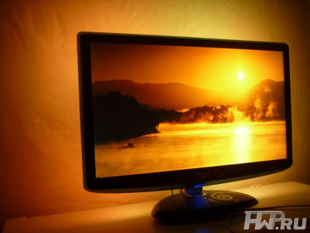
Various special effects from movies and clips, for example, explosions or dynamic chases, look especially beautiful when using the PaintPack module.
We all know how difficult it is to choose gifts for loved ones several times a year. In such situations, manufacturers who produce completely new things come to the rescue. PaintPack is one great example of such a gift. The backlight module is a unique device of its kind. You will probably be surprised that the production of such affordable and universal Ambilight analogues has not yet been mastered in any technically developed country in the world.
Even numerous Chinese electronics factories do not yet produce devices like PaintPack. Therefore, if you are choosing a gift for an advanced computer user, then the PaintPack module will certainly be a pleasant surprise for him, the existence of which he did not know. This gift will be no less pleasant for a child, a girl, and even your parents, who will certainly be pleased with the beautiful lighting of the space behind the monitor.
PaintPack official website -www.paintpack.ru
Roman aka Paintpack
19/12.2011
Today I will tell you and show you how to make dynamic monitor backlighting.
Surely you know that sitting at a computer in the dark is harmful to the eyes, and this is due to the contrast between the monitor and the darkness. Therefore, to reduce eye strain, backlighting is needed. Of course, you can get by with a table lamp, but to create more comfort or just for beauty.


8) Flash the Arduino. The firmware and instructions on how to do this can be found at.


In 2007, Philips patented an incredibly simple, but, without exaggeration, amazing TV backlight technology. With such adaptive backlighting, the eyes become less tired when viewing in the dark, the presence effect increases, the display area expands, etc. Ambilight is applicable not only to video and photo content, but also to games. Ambilight has become a hallmark of Philips TVs. Since then, Philips has been closely vigilant so that none of the major manufacturers would even think of encroaching on the sacred by creating something similar. It is probably possible to license this technology, but the conditions are somehow prohibitive, and other market players are not particularly eager to do this. Small companies also tried (and there are now companies that are doing this) to introduce similar technology in the form of separate kits, but punishment from Philips was inevitable. So, in the best case, if the company does not somehow renew the patent or its derivative, other manufacturers will only be able to produce something similar in 2027.
But such punishment does not apply to us, ordinary consumers. We are free to do what we see fit. Today I will tell you in detail how to make your own adaptive backlight for a TV or monitor like Philips Ambilight (hereinafter simply Ambilight). For some, the article will not contain anything new, because... There are dozens of such projects, and hundreds of articles have been written in different languages, and there are thousands of people who have already done this for themselves. But for many this can all be very interesting. You don't need any special skills. Only basic knowledge of physics for the 8th grade of high school. Well, just a little bit of soldering of wires.
So that you can better understand what I’m talking about, I’ll give you my example of what happened. The real costs for a 42" TV are about 1000 rubles and 2 hours of work.
The video does not convey all the sensations and effect in its entirety, but the children sat with their mouths open for the first time.
The cheapest, simplest and most effective option is a PC running Windows, Mac OS X or Linux as the signal source. Windows boxes on Atom processors, which cost from $70, are now very common. All of them are ideal for implementing Ambilight. I’ve been using various Windows boxes (in a TV stand) as a media player for several years now, I’ve written a small handful of reviews and consider them the best TV set-top boxes for media content. The hardware implementation of this option is the same for all of the listed operating systems. It is this option that I will talk about in the article.. The software part will be related to the Windows system; AmbiBox will act as a universal control program. Can be used with Mac OS X and Linux.
The second option is that the signal source is a media set-top box based on Android, of which there are also a huge number. This option is the most problematic. First, the highlighting will only work in the Kodi media harvester (and its offshoots). Secondly, in the vast majority of cases, everything works only with hardware video decoding disabled, which is unacceptable for most boxes. The hardware implementation of the project also imposes certain requirements. I won’t touch on it, but if there’s something specific you’re interested in, I’ll try to answer in the comments.
The third option is a solution independent of the signal source. This is the most expensive, but absolutely universal solution, because... the signal is taken directly from the HDMI cable. For it you will need a fairly powerful microcomputer (such as a Raspberry Pi), an HDMI splitter, an HDMI-RCA AV converter, a USB 2.0 analog video capture device. Only with this option you can be guaranteed to use Ambilight with any TV set-top box/receiver, Android boxes, Apple TV, game consoles (for example, Xbox One, PlayStation 4) and other devices that have an HDMI output. For the version with 1080p60 support, the cost of components (without LED strip) will be about $70, with 2160p60 support - about $100. This option is very interesting, but a separate article needs to be written on it.
First a little explanation.
WS2811 is a three-channel controller/driver (chip) for RGB LEDs with single-wire control (addressing an arbitrary LED). WS2812B is an RGB LED in an SMD 5050 package, which already has a WS2811 controller built into it.
For simplicity, the LED strips suitable for the project are called WS2811 or WS2812B.
WS2812B strip is a strip on which WS2812B LEDs are placed in series. The strip operates with a voltage of 5 V. There are strips with different densities of LEDs. Usually it is: 144, 90, 74, 60, 30 per meter. There are different degrees of protection. Most often these are: IP20-30 (protection against solid particles), IP65 (protection against dust and water jets), IP67 (protection against dust and protection against partial or short-term immersion in water to a depth of 1 m). Backing in black and white.
Here is an example of such a tape:

WS2811 tape is a tape on which a WS2811 controller and some kind of RGB LED are placed in series. There are options designed for voltages of 5 V and 12 V. Density and protection are similar to the previous option.
Here is an example of such a tape:

There are also WS2811 “strips” with large and powerful LEDs, as in the photo below. They are also suitable for implementing Ambilight for some huge panel.

Which tape to choose, WS2812B and WS2811?
An important factor is the power supply of the tape, which I will talk about a little later.
If you have a power supply at home that is suitable for power (often power supplies are left at home from old or damaged equipment), then choose a tape based on the voltage of the power supply, i.e. 5 V - WS2812B, 12 V - WS2811. In this case, you will simply save money.
From myself I can give a recommendation. If the total number of LEDs in the system is no more than 120, then WS2812B. If more than 120, then WS2811 with an operating voltage of 12 V. You will understand why this is so when it comes to connecting the tape to the power supply.
What level of tape protection should I choose?
For most, IP65 is suitable, because... On one side it is coated with “silicone” (epoxy resin), and on the other there is a 3M self-adhesive surface. This tape is convenient to mount on a TV or monitor and is convenient to wipe off dust.
What LED density should I choose?
For the project, strips with a density of 30 to 60 LEDs per meter are suitable (of course, 144 is possible, no one prohibits). The higher the density, the greater the Ambilight resolution (number of zones) and the greater the maximum overall brightness. But it’s worth considering that the more LEDs in the project, the more complex the strip’s power supply circuit will be, and a more powerful power supply will be needed. The maximum number of LEDs in a project is 300.
Buying tape
If your TV or monitor is hanging on the wall, and all 4 sides have a lot of free space nearby, then the tape is best placed at the back along the perimeter on all 4 sides for maximum effect. If your TV or monitor is installed on a stand, or there is little free space at the bottom, then the tape should be placed on the back on 3 sides (i.e. the bottom without tape).
For myself, I chose a white WS2812B IP65 strip with 30 LEDs per meter. I already had a suitable 5V power supply. I was deciding whether to use 60 or 30 LEDs per meter, but chose the latter after reviewing the video with ready-made examples of implementation - the brightness and resolution suited me, and the power supply was easier to organize and there were fewer wires. Aliexpress has a huge number of lots of WS2812B tapes. I ordered 5 meters for $16. For my TV (42", 3 sides) I only needed 2 meters, i.e. I could buy it for $10, the remaining three meters for a friend. Prices often change among sellers, there are many offers, so just choose a cheap lot on Aliexpress with a high rating (search keywords - WS2812B IP65 go WS2811 12V IP65).


Buying a power supply for the tape
The power supply is selected according to power and voltage. For WS2812B - voltage 5 V. For WS2811 - 5 or 12 V. The maximum power consumption of one WS2812B LED is 0.3 W. For WS2811 in most cases it is the same. Those. The power supply power must be at least N * 0.3 W, where N is the number of LEDs in the project.
For example, you have a 42" TV, you chose a WS2812B strip with 30 LEDs per meter, you need 3 meters of strip on all 4 sides. You will need a power supply with a voltage of 5 V and a maximum power of 0.3 * 30 * 3 = 27 W , i.e. 5 V / 6 A. My implementation uses only 3 sides, a total of 60 LEDs (57 to be precise) - power from 18 W, i.e. 5 V / 4 A.
I’ve had the ORICO CSA-5U (8 A) multiport USB charger lying idle for a long time, left over from an old review. Its ports are powered in parallel (this is critically important), this charger is ideal for me as a power supply, because... I will connect the tape through 2 parallel connections (explanations will be later in the article).

If I didn’t have this charger, I would have chosen it (there is information that this particular power supply is equipped with 2.5 A internals, so you need to study this issue in more detail with the seller, or look at other models).

Buying a microcomputer
Ambilight will be controlled by an Arduino microcomputer. Arduino Nano on Aliexpress costs about apiece.

Costs for my option (for 42" TV):
$10 - 2 meters WS2812B IP65 (30 LEDs per meter)
$4 - 5 V / 4 A power supply (I didn’t spend any money on a power supply, I’m giving the cost for clarity)
$2.5 - Arduino Nano
-----------
16,5$
or 1000 rubles
Hardware implementation
The most important thing is to properly organize the power supply for the tape. The tape is long, the voltage sags at high currents, especially at 5 V. Most of the problems that arise for those who make their own Ambilight are related to power supply. I use the rule - you need to make a separate power supply for every 10 W of maximum power consumption at 5 V and 25 W of power consumption at 12 V. The length of the power supply (from the power supply to the tape itself) should be minimal (without reserve), especially at 5 IN.
The general connection diagram is as follows (the diagram shows the power connection for my version):

Power is supplied to the tape at both ends - two parallel connections. For example, if I were lighting on all 4 sides, and the strip had 60 LEDs per meter (i.e. maximum power 54 W), then I would make the following power supply:

The connecting wires must be used appropriately; the smaller the gauge (AWG), the better, so that they are sufficient for the calculated current strength.
Two contacts go to the Arduino from the tape. GND, which needs to be connected to the corresponding pin on the Arduino. And DATA, which needs to be connected to the sixth digital pin through a 300-550 Ohm resistor (preferably 470 Ohms). If you don’t have a resistor, then in most cases everything will work fine without it, but it’s better to have one. You can buy a resistor for a couple of kopecks at any radio store. The Arduino microcomputer itself can be placed in any convenient case; many people use a Kinder surprise egg for this. The Arduino should be placed as close to the tape as possible so that the DATA connection has a minimum length.
Soldering wires to the tape is simple. The main rule is that the contact time with the soldering iron should be minimal; you cannot “mess around” with the soldering iron.
In my case it turned out like this:


Two black high-quality USB cables were used for power, and a white one for connecting to the computer. I ran out of white heat shrink tubing so I used red ones. Not as “pretty”, but it suits me (it’s hidden behind the TV anyway).
An important question is how to bend the tape at a right angle? If you have a strip of 60 LEDs, then the strip needs to be cut and connected with short wires (placing it all in a heat-shrinkable tube). You can buy special three-pin corner connectors for LED strips (there are 4 pins in the picture, just for example):

If you have a strip of 30 LEDs, then the distance between the LEDs is large, you can easily make a corner without cutting. Remove a piece of the “silicone” coating, insulate (you can even use tape) the contact pad and bend it according to the diagram:
I cut a piece of tape to practice. The main thing is not to overdo it - bend it slightly once and that’s it. There is no need to bend it here and there, there is no need to press the bend line too hard.

Here is a view from the back of the TV, all the wires go through the hole into the cabinet:

We connect the Arduino microcomputer via USB. The driver (CH340 serial interface) will be installed automatically. If this does not happen, then in the Arduino IDE folder there is a Drivers folder with everything you need.
Launch the Arduino IDE and open the Adalight.ino file.

We change the number of LEDs in the code. I'm 57.

Tools > Board > Arduino nano
Tools > Port > Select the COM port (the desired option will be there)
Click the “Download” button:

The program will inform you when the download is complete (this is literally a couple of seconds).
Ready. You need to disconnect the Arduino from USB and connect it again. The tape will light up sequentially in red, green and blue - the Arduino has been activated and is ready for use.
Download and install the program. In the program, click “More settings” and specify the device - Adalight, COM port and the number of LEDs. Select the number of frames to capture (up to 60).

Next, click “Show Capture Zones” > “Zone Setup Wizard”. Select your ribbon configuration.

Click Apply and Save Settings. This completes the basic settings. Then you can experiment with the size of the capture zones, color correct the tape, etc. The program has many different settings.

To activate a profile, just double-click on the corresponding icon (AmbiBox profiles) in the Windows notification area. The tape will light up immediately. It can also be turned off by double clicking.
That's basically it. You saw the result at the beginning of the article. Nothing complicated, cheap and healthy. I'm sure you can do better, so share your crafts in the comments.
The proprietary backlighting technology of the above-mentioned company consists of special lamps built into the TV that allow a soft glow to be projected in a certain way onto the wall behind the TV, which seems to continue the picture from the screen to increase immersion in the atmosphere of what is happening on the screen.
The technology itself was born in the last century due to the fact that, on the one hand, the brightness of the then TV receivers was insufficient, and viewers turned off the lights when watching them, on the other hand, watching TV in the dark put a sharp strain on the eyes, which led to rapid fatigue and general discomfort. The solution was obvious - the presence of a nearby source of diffused light (so-called TV lamps). Today, according to the Philips research department, Ambilight technology is designed to solve this problem.
Currently, there are already 5 generations (and a lot of modifications) of this technology, of which the last three are the most common:
All technologies, to one degree or another, create diffuse light from behind the TV, which complements the colors and light intensity of the image displayed on the screen.
What can you say at the end of the review? The device is undoubtedly interesting and worth trying, especially considering that the manufacturer provides a free test drive for 30 days, i.e. if you don’t like the device, you can return it and get your money back. Your costs in this case will be equal to postage to the manufacturer. The main drawback is that the device only works in conjunction with software, which means you need a computer to get the dynamic backlight effect.
Well, the bottom line is:
As you know, it is not recommended to watch TV in complete darkness to protect your eyesight. And with overhead light - I don’t like it - it’s too bright. When watching TV, I turn on the floor lamp and everything seems to be fine, but I wanted to organize lighting for the corner where the TV is. And don't let it shine in your eyes. Well, like one well-known company - Ambilight technology.
For this purpose, I purchased a warm white LED strip powered by USB, because... I didn’t want to bother with the separate on/off switch of this very backlight. Well, why didn’t I take an RGB strip - I’m quite happy with the white mono light and don’t need another remote control on the sofa. Well, here, as they say, who wants what - choose for yourself.
The tape came in a bag, wound on a reel, total weight - 45 grams. 
I ordered the length of the tape - 2m. I decided to place it on three sides (except the bottom) of a 46-inch TV. I think this will be enough for normal lighting.
The tape shines quite brightly from the USB connector 

As you can see, the tape consists of a base with LEDs and resistors applied to it. On the reverse side there is double-sided tape. 
There are 120 LEDs located on two meters. 
Started with fitting 
These same 120 diodes were distributed as follows: top - 60 pieces, right and left - 30 each. 
Since it’s impossible to bend the tape normally and beautifully at 90 degrees at the corners of the TV, I cut it into these same 3 parts. Fortunately, the places where you can cut are indicated (see photo above).
I applied the tape to the selected and previously degreased areas. Then, taking precautions, I soldered these parts 
All that remains is to connect the design to the standard USB port of the TV 
And - here it is, what I wanted, rear view 
And now - in front 
Well, a little on top, just in case 
As intended, the backlight turns on when you turn on the TV and turns off with it. No unnecessary movements.
It took about an hour to do everything without rushing, including cleaning the work area and tools.
I “drove” the homemade product a little - the diodes practically did not heat up, you couldn’t feel it with your finger. I have doubts about the reliability of the supplied adhesive tape, I don’t know how it is? If necessary, I think it will be easy to replace with something stronger (I mean good tape).
Somehow like this. Good luck to all.


