We repair the engine

Before installing new pistons on the engine, you should carefully study their markings and select them so that they completely match in class and weight. All markings are applied with a stamp on the bottom of the piston.
Marking of piston and connecting rod;
First, pistons can vary in outer diameter. There are five classes: A,B,C,D,E. The difference in diameters between adjacent classes is 0.01 mm. Since the outside of the piston has a complex shape, it is necessary to measure its diameter only in a plane that is perpendicular to the piston pin - at a distance of 51.5 mm from the piston head.
Secondly, pistons are divided according to the diameter of the piston pin hole. There are three classes: class 1, class 2 and class 3. The pitch between them is 0.004 mm. In accordance with this, markings in the form of colored stripes are also present on the end of the piston pins. A blue mark means that the piston pin belongs to the first class, a green mark to the second, and a red mark to the third. There are three groups of pistons by weight: normal, plus 5 grams, minus 5 grams. On one engine, pistons should only be installed with the same values masses. As for repair size pistons, they are manufactured with an increased outer diameter and come in two types: the diameter of the first is increased by 0.4 mm, the second by 0.8 mm. A value of 0.4 mm corresponds to a mark in the form of a triangle on the piston bottom, and a value of 0.8 mm corresponds to a mark in the form of a square. Repair size rings have the same size ranges and are marked “40” and “80” respectively.
Also, a mark in the form of an arrow 2) is applied to the piston bottom. It serves as a guide when installing it in the engine cylinder and should point towards the camshaft drive.
Another marking that is intended to help us when assembling the engine is the numbers on the connecting rods and covers. They indicate the number of the cylinder in which they are installed and must match, since the connecting rods are processed together with the caps and are not interchangeable.
For new parts, the gap between the cylinder and the piston should be 0.025-0.045 mm. This is achieved by installing pistons of the same class as the cylinders. In case of severe wear of parts, the maximum gap value that can be allowed is 0.15 mm. If its value is higher, you need to select new pistons. Pistons of classes A, C and E are manufactured as spare parts. Considering the slight overlap of sizes, these three classes are quite enough to select pistons for absolutely any cylinder when repairing an engine. So, for example, a “C” class piston can fit “B” and “D” class cylinders, or worn “A” and “B” class cylinders
On the bottom of the piston there is a designation of the piston group according to the diameter of the skirt, on the front part of the piston - the repair group and the repair size of the piston. To facilitate the individual selection of pistons to cylinders, each of the sizes of the repair group is divided into size groups, in which the sizes of the pistons along the skirt diameter follow every 0.01 mm. All operations for selecting pistons for cylinders must be carried out at a temperature environment 17...23 °C.
To facilitate the individual selection of piston pins, pistons are divided into four size groups according to the diameter of the piston pin hole. Marking of the size group according to the diameter of the holes for the piston pin is carried out by applying paint to the piston boss.
When replacing pistons without replacing the cylinder liner, it is advisable to treat the upper edge (shoulder) of the liner, which was formed as a result of wear of the liner under the upper piston ring, with a scraper or a fine-grained grinding wheel mounted on a pneumatic or electric drill.
Pistons to cylinders should be selected so that the gap between the cylinder wall and the piston skirt is 0.03...0.05 mm. The gap is determined by a feeler tape with a thickness of 0.08 mm, a width of 10 ... 13 mm and a length of at least 200 mm. The feeler tape is pulled through the gap between the piston and the cylinder with the piston stationary with a force of 25 ... 45 N. In this case, the piston should be facing downwards, and the feeler tape should be in a plane perpendicular to the axis of the hole for the piston pin. The selection of pistons can be carried out without pressing the liners out of the block or after they have been pressed out. After selecting the pistons to the cylinder liners, it is necessary to knock out the serial numbers of the cylinders on the piston bottoms.
The pin is seated in the piston bosses with an interference fit of 0.0025… 0.0075 mm. The cylindrical tolerance of the pin is 0.00125 mm in radius terms. The piston pin retaining rings should be installed in the piston grooves with some interference, i.e. they should not turn by hand. Rings that have lost their elasticity should be replaced.
The lower head of the connecting rod is processed as an assembly with the cover, therefore, during disassembly, inspection and assembly, the completeness of the connecting rod and the connecting rod cover should be maintained. The connecting rod caps are centered on the ground surfaces of the connecting rod bolts. Repairing the upper head of the connecting rod usually involves pressing out, pressing in and boring the bushing. The bushing pressing force must be at least 7,000 N. When repairing the upper head of the connecting rod, the dimensions for the bushing and pin must correspond to the dimensions recommended by the manufacturer. To select a pair of piston pin - connecting rod, the dimensions of the upper head of the connecting rod (the diameter of the hole for the bushing) are divided into size groups that differ from each other by 0.0025 mm.
Rice. Selection of the piston to the liner using a feeler tape:
a - the liner is pressed into the cylinder block; b - the liner is pressed out of the cylinder block
To assemble the connecting rod with the piston, you need to match the piston pin to the bushings of the upper head of the connecting rod and the piston bosses. To connect to the connecting rod, the piston is heated in oil or in an electric heater to a temperature of 55 °C. In this case, the finger should enter the hole in the boss of the heated piston smoothly from the force of the thumb right hand. In such a connection, after cooling the piston, the required interference of 0.0025 ... 0.0075 mm appears.
Then you need to check the serial numbers of the pistons and connecting rods. The connecting rod is secured in a vice, the piston is installed, and their connection is fixed with a finger. When assembling the piston with the connecting rod, it must be installed so that the mark on the piston bottom is directed towards the front of the engine. The boss stamped on the connecting rod for the left bank of cylinders should also be directed towards the front of the engine, i.e. in one direction with the mark on the piston. For the right group of cylinders, when assembling the piston with the connecting rod, the connecting rod boss should be directed towards the rear of the engine, and the mark on the piston crown should be directed towards the front.
After connecting and checking the connecting rod and piston group, secure the pin in the piston bosses with retaining rings, then carefully wipe the pins matched to the grooves and fitted to the cylinders piston rings and install them on the pistons using a special tool. The pistons and connecting rod assembly must be checked for weight. Parts of a kit installed on one engine should not differ in weight by more than 12 g, i.e. The connecting rods must correspond in weight to one group. To install pistons with connecting rods into the cylinders of the block, you need to perform the following operations:
Then you need to check and blow out the hole in the lower head of the connecting rod, which serves to spray oil onto the cylinder walls, insert the liners into the connecting rod and into the cover, wipe the upper connecting rod liners and the piston with a napkin, install the rings on the piston, placing the internal groove upward, move the joints of the compression rings apart piston circumference by approximately 120°. After installation, separate the joints of the compression rings by 180°.
Next, wipe the cylinder liners of the block and the connecting rod journal with a napkin, lubricate the surface of the connecting rod bearing, piston, piston rings and cylinder liners with clean oil used for the engine, insert the piston with the connecting rod into the cylinder, pointing the mark on the bottom of the piston to the front of the engine using a special fixtures, bring the connecting rod bearings to the crankshaft journal, moving the piston along the cylinder using a wooden mandrel, lubricate the shaft journal with oil and tighten the lower head to it, remove the safety tips from the connecting rod bolts and replace the lower connecting rod cover, securing it with connecting rod nuts.
Before completing assembly, you need to check the total axial clearance between the ends of the connecting rods and the crankpin of the crankshaft using a feeler gauge and finally tighten the connecting rod bearing bolts with a torque wrench. After tightening each pair of connecting rod bearings, rotate the crankshaft. The rotation torque of the shaft with correctly selected radial clearances in the bearings should be no more than 100 Nm. Similar operations must be carried out when installing the remaining pistons with connecting rods into the cylinders.
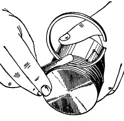
Carbon deposits are removed from the bottom with a blunt metal scraper or a metal brush, having previously moistened the carbon deposits with kerosene.
Carbon deposits are removed from the grooves using a special device. The presence of cracks in the piston is determined by ear, for which the piston is taken by the head and light blows are applied to the skirt metal object. A dull, rattling sound indicates the presence of cracks.
Rice. A device for removing carbon deposits from piston grooves.
Pistons with large diameter wear, cracks and deep scratches must be replaced. Worn grooves for piston rings can be machined to accommodate an increased ring height by lathe using a device that is a ring with an outer diameter equal to the inner centering belt of the piston. The piston is placed on the ring installed in the machine chuck and secured with an eye bolt. The eye bolt is connected to the piston by means of a piston pin and passes through the machine spindle. WITH reverse side the bolt is secured with a nut. The grooves on the piston should be machined taking into account the established repair dimensions of the piston rings.
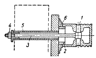
Rice. Installing the piston when turning piston grooves:
1 - piston pin; 2 - installation ring; 3 - eye bolt; 4 - nut; 5 — machine spindle; 6 - machine chuck.
Worn holes in the bosses are repaired by reaming them to fit the increased diameter of the piston pin using a sliding reamer with a guide shank. The use of short reamers is unacceptable, as this easily leads to a violation of the perpendicularity of the pin axis with the piston axis; therefore, after deployment, it is necessary to check the perpendicularity of the axes using a special device.
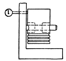
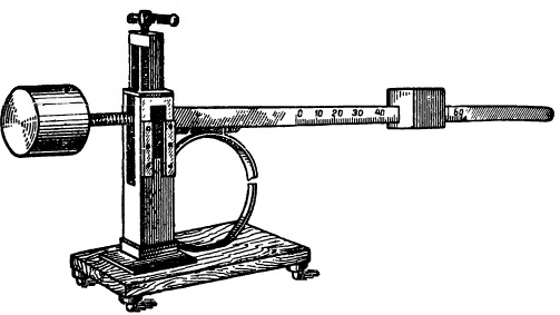
Rice. Checking the perpendicularity of the piston pin axis.
The piston is put on the finger of the device and moved close to the rack. In this case, the indicator pin attached to the rack comes into contact with the piston, and the indicator arrow will give a certain deflection. Having noticed the indicator readings, the piston is removed and put on the finger with the other side. The difference in indicator readings should not exceed 0.05 mm. Otherwise, the piston must be rejected.
Pistons are selected in accordance with the repair dimensions of the cylinders. The number for increasing the piston diameter is stamped on its bottom. Each piston is selected individually for the cylinder to obtain required clearance. The gap size is determined by pulling a feeler tape between the piston and cylinder using a dynamometer on the side opposite to the skirt cut. The force on the dynamometer when the probe moves through the gap must be within the specified limits.
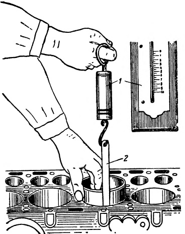
Rice. Checking the gap between the piston and cylinder:
1 - dynamometer; 2 - probe tape.
In the absence of a feeler tape, the piston is selected so that it passes freely along the entire length of the cylinder under light hand pressure, but does not move under its own weight when the cylinder is in a vertical position. In addition to the clearance, when selecting pistons, their weight is also taken into account. The difference in weight of aluminum pistons of one set should be no more than 5 g.
When the surface of the rings wears out and there is loss of elasticity, the rings are replaced with new ones of a repair size corresponding to the repair size of the piston and cylinder. The number for the repair increase in the diameter of the piston ring is stamped on its end surface near the lock. The new ring is selected according to the cylinder and piston.
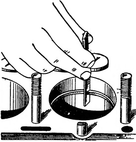
Rice. Checking the gap at the piston ring joint.
To select a ring for a cylinder, you need to install it in the cylinder, align it with a piston and measure the gap at the joint with a feeler gauge. If there is no gap or it is small, then file the joint to a normal size. If the gap is larger than normal, then the ring is unsuitable for this cylinder.
Rice. Measuring the gap in the piston ring groove.
To select a ring for the piston, you must first “roll” it in a circle along the piston groove, and then use a feeler gauge to measure the gap in the piston ring groove. If the ring is stuck in a groove or there is a small gap, the end part of the ring is ground by hand on a sheet sandpaper mounted on a flat wooden slab.
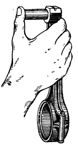
The elasticity of the rings is checked for special device. In this case, the magnitude of the load must correspond to the gap at the joint of the ring installed in the cylinder.
Rice. Checking the elasticity of the piston ring.
Piston pins with wear in diameter of more than 0.5 mm must be replaced, and those with wear of less than 0.5 mm are restored by regrinding to a smaller size (if the pin was oversized), chrome plating or expansion.
The pin is ground on a cylindrical grinder or lathe using a special support-grinding device. This device consists of an electric motor with a grinding stone, it is fixed in the support of the lathe.
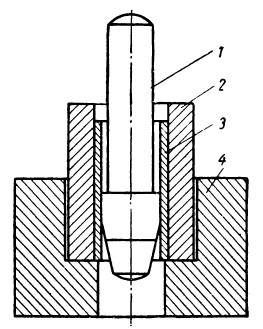
Rice. Piston pin extension:
1 - mandrel; 2 - matrix; 3 - piston pin; 4 - base.
The original size of the finger is restored by chrome plating or spreading. Dispensing is carried out in a special device consisting of a base, a matrix and a mandrel (punch). The finger is heated to a temperature of 800-900° and installed in the matrix, then a mandrel is driven inside the finger under pressure from a press or with hammer blows. The matrix limits the extension of the finger and gives it correct form. After distribution, the finger is subjected to quenching in oil, followed by tempering and ground to the nominal size.
A repaired or new piston pin is selected according to the connecting rod bushing and the holes of the piston bosses.
Device Features
Completing and assembling a piston with a connecting rod for a VAZ engine
Piston made from aluminum alloy and coated with a layer of tin to improve run-in. piston skirt cross section oval and conical in height. For this reason, it is extremely important to measure the piston diameter only in a plane perpendicular to the piston pin and at a distance of 52.4 mm from the piston crown.
The hole for the piston pin is shifted from the axis of symmetry by 2 mm to the right side of the engine. For this reason for correct installation the piston into the cylinder near the hole for the piston pin there is a mark “П”, which should be facing towards the front of the engine.
Pistons of repair sizes since 1986 ᴦ. for all engine models they are manufactured with an outer diameter increased by 0.4 and 0.8 mm. Until 1986 ᴦ. pistons of the following repair sizes were produced: for engines 2101 and 2103 - with an increase of 0.2; 0.4 and 0.6 mm; for 2105 and 21011 - with an increase of 0.4 and 0.7 mm.
Piston rings made of cast iron. The outer surface of the upper compression ring is chrome plated and has a barrel shape. The lower compression ring is of the scraper type (with a groove along outer surface), phosphated. The oil scraper ring has slots for oil removed from the cylinder and an internal coil spring (expander).
Piston pin- steel, tubular cross-section, pressed into the upper head of the connecting rod and rotates freely in the piston bosses.
connecting rod- steel, forged, with a split lower head in which the connecting rod bearing shells are installed. The connecting rod is processed together with the cover; therefore, during assembly, the numbers on the connecting rod and the cover must be the same.
The calculated gap between the piston and cylinder (for new parts) is 0.05-0.07 mm. It is determined by measuring the cylinders and pistons and is ensured by installing pistons of the same class as the cylinders. The maximum permissible gap (in case of wear of parts) is 0.15 mm. Note. The piston diameter is measured in a plane perpendicular to the piston pin, at a distance of 52.4 mm from the piston crown. According to the outer diameter, the pistons are divided into five classes (A, B, C, D, E) every 0.01 mm, and according to the diameter of the piston pin hole - into three categories every 0.004 mm. The piston class (letter) and the piston pin hole category (number) are stamped on the piston bottom.
If a used engine has a gap exceeding 0.15 mm, then it is extremely important to re-select the pistons to the cylinders so that the gap is as close as possible to the calculated one.
Spare parts include pistons of classes A, C, E. These classes are sufficient to select a piston for any cylinder during engine repair, since pistons and cylinders are divided into classes with a slight overlap of sizes.
Assembly . Before assembly, fit the pin to the piston and connecting rod. For new parts, the class of pin holes in the connecting rod and piston must be identical to the class of the pin. For used parts, for proper mating it is extremely important that the piston pin, lubricated with engine oil, fits into the bore of the piston or connecting rod by simply pressing the thumb and does not fall out of it. Replace the finger that falls out with another one of the next category. If a third category pin was inserted into the piston, replace the piston pin and connecting rod.
Assembly of the connecting rod and piston group is carried out in the reverse order of disassembly. After installing the piston pin, lubricate it with engine oil through the holes in the piston bosses. Install the piston rings in the following order. Lubricate the piston grooves and piston rings with engine oil. Orient the piston rings so that the upper compression ring lock is at an angle of 45° to the piston pin axis, the lower compression ring lock is at an angle of approximately 180° to the upper compression ring lock axis, and the oil scraper ring lock is at an angle of approximately 90° to the axis locking the upper compression ring. Install the lower compression ring with the groove facing down. If the ring is marked “Top” or “TOP”, then install the ring with the mark up (towards the piston bottom). Before installation oil scraper ring check that the joint of the spring expander is located on the side opposite to the ring lock.
Device Features
Completing and assembling a piston with a connecting rod for a VAZ engine
Piston Made of aluminum alloy and coated with a layer of tin to improve wearability. The piston skirt is oval in cross section and conical in height. Therefore, it is necessary to measure the piston diameter only in a plane perpendicular to the piston pin and at a distance of 52.4 mm from the piston bottom.
The hole for the piston pin is shifted from the axis of symmetry by 2 mm to the right side of the engine. Therefore, for proper installation of the piston into the cylinder, there is a “P” mark near the hole for the piston pin, which should be facing towards the front of the engine.
Since 1986, repair size pistons for all engine models have been manufactured with an outer diameter increased by 0.4 and 0.8 mm. Until 1986, pistons of the following repair sizes were produced: for engines 2101 and 2103 - with an increase of 0.2; 0.4 and 0.6 mm; for 2105 and 21011 - with an increase of 0.4 and 0.7 mm.
Piston rings made of cast iron. The outer surface of the upper compression ring is chrome plated and has a barrel shape. The lower compression ring is of the scraper type (with a groove along the outer surface), phosphated. The oil scraper ring has slots for oil removed from the cylinder and an internal coil spring (expander).
Piston pin- steel, tubular cross-section, pressed into the upper head of the connecting rod and rotates freely in the piston bosses.
connecting rod- steel, forged, with a split lower head in which the connecting rod bearing shells are installed. The connecting rod is processed together with the cover, so during assembly the numbers on the connecting rod and the cover must be the same.
The calculated gap between the piston and cylinder (for new parts) is 0.05-0.07 mm. It is determined by measuring the cylinders and pistons and is ensured by installing pistons of the same class as the cylinders. The maximum permissible gap (if parts are worn) is 0.15 mm.
Note. The piston diameter is measured in a plane perpendicular to the piston pin, at a distance of 52.4 mm from the piston crown.
According to the outer diameter, the pistons are divided into five classes (A, B, C, D, E) every 0.01 mm, and according to the diameter of the piston pin hole - into three categories every 0.004 mm. The piston class (letter) and the piston pin hole category (number) are stamped on the piston bottom.
If a used engine has a gap exceeding 0.15 mm, then it is necessary to re-select the pistons to the cylinders so that the gap is as close as possible to the calculated one.
Spare parts include pistons of classes A, C, E. These classes are sufficient to select a piston for any cylinder when repairing an engine, so
how pistons and cylinders are divided into classes with slight size overlap.
Assembly . Before assembly, fit the pin to the piston and connecting rod. For new parts, the class of pin holes in the connecting rod and piston must be identical to the class of the pin. For used parts, for proper mating it is necessary that the piston pin, lubricated with engine oil, enters the hole of the piston or connecting rod by simply pressing the thumb and does not fall out of it. Replace the finger that falls out with another one of the next category. If a third category pin was inserted into the piston, replace the piston pin and connecting rod.
Assembly of the connecting rod and piston group is carried out in the reverse order of disassembly. After installing the piston pin, lubricate it with engine oil through the holes in the piston bosses. Install the piston rings in the following order. Lubricate the piston grooves and piston rings with engine oil. Orient the piston rings so that the upper compression ring lock is at an angle of 45° to the piston pin axis, the lower compression ring lock is at an angle of approximately 180° to the upper compression ring lock axis, and the oil scraper ring lock is at an angle of approximately 90° to the axis locking the upper compression ring. Install the lower compression ring with the groove facing down. If the ring is marked “TOP” or “TOP”, then install the ring with the mark facing up (towards the piston bottom). Before installing the oil scraper ring, check that the joint of the spring expander is located on the side opposite to the ring lock.
.jpg)


