1. Rules for the preparation of architectural and construction drawings (according to GOST 21.501-93): implementation of the building plan.
General information.
Basic and working drawings are made in line drawings, using lines of different thicknesses, thereby achieving the necessary expressiveness of the image. In this case, the elements included in the section are highlighted with a thicker line, and the visible areas beyond the section are highlighted with a thinner line. The smallest thickness of lines made in pencil is approximately 0.3 mm, in ink - 0.2 mm, the maximum line thickness is 1.5 mm. The thickness of the line is selected depending on the scale of the drawing and its content - plan, facade, section or detail.
Scale images in the drawings should be selected from the following series: for reduction -1:2; 1:5; 1:10; 1:20; 1:25; 1:50; 1: 100; 1: 200; 1: 400; 1: 500; 1: 800; 1: 1000; 1: 2000; 1: 5000; 1:10,000; for magnification - 2:1; 10:1; 20:1; 50:1; 100:1.
The choice of scale depends on the content of the drawing (plans, elevations, sections, details) and the size of the object depicted in the drawing. Plans, facades, sections of small buildings are usually made on a scale of 1:50; drawings of large buildings are carried out on a smaller scale - 1:100 or 1:200; very large industrial buildings sometimes require a scale of 1:400 - 1:500. Components and parts of any buildings are made on a scale of 1:2 - 1:25.
Coordination axes, dimension and extension lines. Coordination axes determine the position of the structural elements of the building, the sizes of steps and spans. The axial lines are drawn with a thin dash-dotted line with long strokes and are marked with marks that are placed in circles.
On building plans, longitudinal axes are usually placed to the left of the drawing, and transverse axes are located below. If the location of the axes of opposite sides of the plan does not coincide, then their markings are placed on all sides of the plan. In this case, the numbering is continuous. The transverse axes are marked with ordinal Arabic numerals from left to right, and the longitudinal ones - in capital letters Russian alphabet (except E, Z, J, O, X, Y, E) down up.
The diameter of the circles must correspond to the scale of the drawing: 6 mm - for 1:400 or less; 8 mm - for 1:200-1:100; 10 mm - for 1:50; 12 mm - for 1:25; 1:20; 1:10..
The font size for axes should be larger size font of the dimensional numbers used in the drawing by 1.5-2 times. Marking of axes on sections, facades, components and parts must correspond to the plan. To apply dimensions, dimension and extension lines are drawn in the drawing. Dimension lines (external) are drawn outside the outline of the drawing in an amount from two to four in accordance with the nature of the object and the design stage. On the first line from the drawing the dimensions of the smallest divisions are indicated, on the next ones - the larger ones. On the last dimension line indicate overall size between the extreme axes with these axes tied to the outer edges of the walls. Dimension lines should be drawn so that the drawing itself is not difficult to read. Based on this, the first line is drawn at a distance from the drawing no closer than 15-21 mm. The distance between the dimension lines is 6-8 mm. Segments on dimension lines corresponding to the dimensions of external wall elements (windows, piers, etc.) are limited by extension lines, which should be drawn starting at a short distance (3-4 mm) from the drawing, until they intersect with the dimension line. The intersections are recorded with notches having a slope of 45°. For very closely spaced small dimensions in the drawings of parts and assemblies, serifs may be replaced with dots. Dimension lines should protrude beyond the outer extension lines by 1-3 mm.
The internal dimension lines indicate the linear dimensions of the premises, the thickness of the partitions and interior walls, width of door openings, etc. These lines should be drawn at a sufficient distance from the internal edges of walls or partitions so as not to make it difficult to read the drawing.  Rules for preparing plan drawings in accordance with the requirements of ESKD and SPDS (schematic drawing): a - coordination axes; b - dimension lines; in-leader lines; g - area of premises; d - cut lines (dimensions are given in millimeters).
Dimension and extension lines are drawn with a thin solid line. All dimensions are given in millimeters without dimension designation. The numbers are placed above the dimension line parallel to it and, if possible, closer to the middle of the segment. The height of the numbers is selected depending on the scale of the drawing and must be at least 2.5 mm when done in ink and 3.5 mm when done in pencil. ^
Level marks and slopes. Marks determine the position of architectural and structural elements on sections and facades, and on plans - in the presence of differences in floor levels. Level marks are counted from a conventional zero level, which for buildings is usually taken to be the level of the finished floor or top edge ceilings of the first floor. Marks below zero are indicated with a “-” sign, marks above zero are indicated without a sign. The numerical value of the marks is given in meters with three decimal places without indicating the dimension. 
Rules for applying marks, dimensions and other designations on sections in accordance with the requirements of ESKD and SPDS (schematic drawing). To indicate a mark on facades, sections and sections, use a symbol in the form of an arrow with the sides inclined to the horizontal at an angle of 45°, based on the contour line of the element (for example, the edge of the plane of the finished floor or ceiling) or on the extension line of the level of the element (for example, the top or the bottom of a window opening, horizontal projections, external walls). In this case, marks of external elements are taken outside the drawing, and internal elements are placed inside the drawing. 
On the plans, marks are made in a rectangle or on a leader line shelf indicating the “+” or “-” sign. On architectural plans, marks are usually placed in a rectangle; on structural drawings to indicate the bottom of channels, pits, and various openings in floors - on a leader line. 
The magnitude of the slope on sections should be indicated in the form of simple or decimal(up to the third character) and denoted by a special sign, sharp corner which is directed towards the slope. This designation is placed above the contour line or on the shelf of the leader line 

On the plans, the direction of the slope of the planes should be indicated by an arrow indicating the magnitude of the slope above it
Designation of cuts and sections shown by an open line (trace of the beginning and end of the cutting plane), which is taken out of the image. With a complex broken section, traces of the intersection of cutting planes are shown
At a distance of 2-3 mm from the ends of the open line outside the drawing, arrows are drawn that indicate the direction of view. Sections and sections are marked with numbers or letters of the Russian alphabet, which are located under the arrows in the cross sections and on the side with outside shooter - in longitudinal. For the design and dimensions of the arrows, see the figure on the right. ^
Designation of premises areas. Areas expressed in square meters with two decimal places without dimension designation, are usually placed in the lower right corner of the plan of each room. The numbers underline. In the drawings of residential building projects, in addition, the residential and usable (total) area of each apartment is marked, which is indicated by a fraction, the numerator of which indicates the residential apartment area, in the denominator - useful. The fraction is preceded by a number indicating the number of rooms in the apartment. This designation is placed on the plan of a large room or, if the drawing area allows, on the plan of the front room. ^
Callouts, explaining the names of individual structural parts in the nodes, are placed on a broken leader line, the inclined section of which with a dot or arrow at the end faces the part, and the horizontal section serves as a shelf - the basis for the inscription. If the drawing is on a small scale, it is allowed to end the leader line without an arrow or a dot. Inscriptions for multilayer structures are applied in the form of so-called “flags”. The sequence of inscriptions relating to individual layers must correspond to the order of the layers in the structure from top to bottom or from left to right. The thickness of the layers is indicated in millimeters without dimension. Marks of structural elements on layout diagrams are applied on the shelves of leader lines. It is allowed to combine several leader lines with a common shelf or place a mark without a leader next to the image of the elements or within the outline. The font size for designating brands must be larger than the font size of the dimensional numbers on the same drawing 
Marking nodes and fragments - important element design of drawings to help them read. The main purpose of marking is to connect nodes and fragments taken out on a larger scale with detailed areas in the main drawing
When moving out nodes, the corresponding place on the facade, plan or section is marked with a closed solid line (circle or oval) indicating on the shelf the leader line with a number or letter of the serial number of the element being taken out. If the node is located on another sheet, then under the shelf of the leader line you should indicate the number of the sheet on which the node is placed 
Above the image or on the side of the removed node (regardless of which sheet it is placed on) there is a double circle indicating the serial number of the node. Diameter of circles 10-14 mm
Technical construction drawings are accompanied by names of individual images, text explanations, specification tables, etc. For these purposes, a standard straight font with a letter height of 2.5 is used; 3.5; 7; 10; 14 mm. In this case, the font height is 5; 7; 10 mm is used for the names of the graphic part of the drawing; 2.5 and 3.5 mm high - for text material (notes, filling out a stamp, etc.), 10 and 14 mm high - mainly for the design of illustrative drawings. The names of the images are located above the drawings. These names and headings of text explanations are underlined line by line with a solid line. The headings of specifications and other tables are placed above them, but not underlined.
^ Floor plan.
In the names of plans in the drawings, it is necessary to comply with the accepted terminology; on architectural plans the finished floor mark or floor number should be indicated, for example “Plan at elevation. 0.000”, “Plan of 3-16 floors”, it is allowed to indicate the purpose of the floor premises in the names of the plans, for example “Plan of the technical underground”, “Plan of the attic”
Floor plan depicted as a section by a horizontal plane passing at the level of window and doorways(slightly above the window sill) or 1/3 of the height of the depicted floor. When there are multi-tiered windows on one floor, the plan is depicted within window openings lower tier. All structural elements, falling into the section (steles, pillars, columns), are outlined with a thick line
The floor plans are marked with:
1) the coordination axes of the building with a dash-dot thin line;
2) chains of external and internal dimensions, including distances between coordination axes, wall thickness, partitions, sizes of window and door openings (in this case inner dimensions applied inside the drawing, external ones - outside);
3) level marks for finished floors (only if the floors are located at different levels);
4) cut lines (cut lines are drawn, as a rule, in such a way that the cut includes openings of windows, external gates and doors);
5) marking of window and door openings, lintels (marking of gate and door openings is allowed in circles with a diameter of 5 mm);
5) designations of nodes and fragments of plans;
6) names of premises, their area
It is allowed to give the names of premises and their areas in an explication according to Form 2. In this case, instead of the names of the premises, their numbers are indicated on the plans.
Form 2
Explication of premises

Built-in premises and other areas of the building, for which separate drawings are made, are depicted schematically with a solid thin line showing load-bearing structures.
Platforms, mezzanines and other structures located above the cutting plane are depicted schematically with a dash-dot thin line with two dots
^
An example of a floor plan for a residential building:
Floor plan elements.
Walls made of lightweight concrete blocks. ^
Symbol in plan: The wall thickness is a multiple of 100mm. The thickness of the internal (load-bearing) wall is min 200 mm. The thickness of the external walls is 500, 600 mm + 50, 100 mm of insulation. The dimensions of the standard block are 390x190x190mm. ^
The walls are brick. The wall thickness is a multiple of 130mm (130, 250, 380, 510, 640mm). The thickness of the internal (load-bearing) wall is 250, 380 mm. The thickness of the external walls is 510, 640 mm + 50, 100 mm of insulation. Dimensions of ordinary ceramic bricks are 250x120x65(88) mm. ^
Walls made of timber. Wall thickness (150) 180, 220 mm. The thickness of the internal (load-bearing) wall is min 180 mm. The thickness of the external walls is 180, 220 mm. ^
The walls are made of logs. Wall thickness 180, 200, 220 - 320 mm (multiples of 20mm). The thickness of the internal (load-bearing) wall is min 180 mm. The thickness of the external walls is 180 - 320 mm. ^
Walls - wooden frame filled with effective insulation. The thickness of the frame post is 100, 150, 180 mm + 40-50 mm of double-sided cladding. The thickness of the internal (load-bearing) wall is 100 + 40-50 mm. The thickness of the external walls is 150, 180 + 40-50 mm. Partitions:


made of lightweight concrete blocks, thickness 190mm;

brick, thickness 120mm;

three-layer wooden, thickness 75mm;

plasterboard metal frame, thickness 50-70mm.
Window openings:

V brick walls;

in timber, log and frame walls.
External doorways:
in walls made of lightweight concrete blocks;

brick walls;

and frame walls. Internal doorways:

for all types of walls.
 A building or any structure in plan is divided by conventional center lines into a number of segments. These lines defining the position of the main load-bearing structures are called longitudinal and transverse coordination axes.
The interval between the coordination axes in the building plan is called the step, and in the predominant direction the step can be longitudinal or transverse.
If the distance between the coordinate longitudinal axes coincides with the span, floor or coating of the main supporting structure, then this interval is called a span.
For floor height N This is the distance from the floor level of the selected floor to the floor level of the floor above. The height of the upper floor is determined using the same principle, whereby the thickness of the attic floor is assumed to be conditionally equal to the thickness of the interfloor floor c. In industrial one-story buildings, the height of the floor is equal to the distance from the floor to the bottom surface of the coating structure.
In order to determine relative position parts of the building use a grid of coordination axes that defines the load-bearing structures of the building.
Drawing of coordination axes.
Coordination axes are dashed with thin dotted lines and marked inside circles with a diameter of 6 to 12 mm. The diameter of the circles must correspond to the scale of the drawing: 6 mm - for 1:400 or less; 8 mm - for 1:200 - 1:100; 10 mm - for 1:50; 12 mm for 1:25; 1:20; 1:10. The direction of marking of axes is applied from left to right, horizontally and from bottom to top, vertically.
If the coordination axes of opposite sides of the plan do not coincide, the designations of the indicated axes in the places of discrepancy are additionally applied on the top and/or right sides. For individual elements located between the coordination axes of the main load-bearing structures, additional axes are drawn and designated as a fraction:
It is allowed to assign numerical and letter designations to the coordination axes of half-timbered columns in continuation of the designations of the axes of the main columns without an additional number.

The binding of coordination axes occurs according to the rules described in paragraph 4 GOST 28984-91. Example:
Tying load-bearing walls from piece materials to the coordination axes should be carried out in compliance with the following rules:
When supporting floor slabs over the entire thickness of the load-bearing wall, it is allowed to combine the outer coordination plane of the walls with the coordination axis (Figure 9d).

Marking of coordination axes.
Coordination axes are marked in Arabic numerals and capital letters, with the exception of the symbols: 3, J, O, X, S, b, b. The numbers indicate the axes on the side of the building with the largest number of coordination axes. Axes markings are usually located on the left and bottom sides of the building plan. The height of the font indicating the coordination axes is chosen to be one or two numbers larger than the size of the numbers on the same sheet. Gaps in digital and letter designations of coordination axes are not allowed.
In the image of a repeating element attached to several coordination axes, the coordination axes are designated in accordance with the figure:
If necessary, the orientation of the coordination axis to which the element is attached in relation to the adjacent axis is indicated in accordance with the figure.
An axis is a central straight line in the form of an imaginary straight line of an object or product.
The axle drawing is carried out on the basis of GOST 2.109-73 - a unified system of design documentation (ESKD).
You can download this simple drawing for free to use for any purpose. For example, for placement on a nameplate or sticker.
How to draw a drawing:
You can draw a drawing either on a sheet of paper or using specialized programs. No special engineering knowledge is required to complete simple sketch drawings.
A sketch drawing is a drawing made “by hand”, observing the approximate proportions of the depicted object and containing sufficient data for the manufacture of the product.
The design drawing with all the technological data for manufacturing can only be completed by a qualified engineer.
To designate in the drawing, you must perform the following operations:
1. Draw an image;
2. Add dimensions (see example);
3. Indicate for production (more about technical requirements read below in the article).
It is most convenient to draw on a computer. Subsequently, the drawing can be printed on paper using a printer or plotter. There are many specialized programs for drawing on a computer. Both paid and free.
Drawing example:
This image shows how simple and quickly drawing can be done using computer programs.
List of programs for drawing on a computer:
1. KOMPAS-3D;
2. AutoCAD;
3. NanoCAD;
4. FreeCAD;
5. QCAD.
Having studied the principles of drawing in one of the programs, it is not difficult to switch to working in another program. Drawing methods in any program are not fundamentally different from each other. We can say that they are identical and differ from each other only in convenience and the presence of additional functions.
Technical requirements:
For the drawing it is necessary to indicate dimensions sufficient for manufacturing, maximum deviations and roughness.
The technical requirements for the drawing should indicate:
1) Manufacturing and control method, if they are the only ones that guarantee the required quality of the product;
2) Indicate a specific technological method that guarantees that certain technical requirements for the product are met.
A little theory:
A drawing is a projection image of a product or its element, one of the types of design documents containing data for the production and operation of the product.
A drawing is not a drawing. The drawing is made according to the dimensions and scale of the real product (structure) or part of the product. Therefore, to carry out drawing work, the work of an engineer with sufficient experience in producing drawing work is necessary (however, to beautifully display a product for booklets, it is quite possible that you will need the services of an artist who has an artistic view of the product or part of it).
A drawing is a constructive image with necessary and sufficient information about dimensions, manufacturing method and operation. You can download the drawing presented on this page for free.
A drawing is an artistic image on a plane created by means of graphics (brush, pencil or specialized program).
A drawing can be either an independent document or part of a product (structure) and technical requirements related to surfaces processed together. Instructions for joint processing are placed on all drawings involved in the joint processing of products.
For more information on drawings, technical requirements for design and indication of manufacturing methods, see GOST 2.109-73. See the list of standards for the development of design documentation.
Information for ordering drawings:
In our design organization You can create any product (both parts and assemblies), which will include an axle drawing as an element of the design documentation of the product as a whole. Our design engineers will develop documentation in the shortest possible time in strict accordance with your technical specifications.
The construction of the main elements of buildings is carried out using modular coordination of dimensions in construction (MDCS), according to which the dimensions of the main space-planning elements of the building must be a multiple of the module.
The main module is assumed to be 100 mm.
Main structural elements ( load-bearing walls, columns) buildings are located along modular coordination axes(longitudinal and transverse). The distance between coordination axes in low-rise buildings is taken as multiples of the 3M module (300 mm).
To determine the relative position of building elements, it is used grid of coordination axes.
Coordination axes are drawn with dash-dot thin lines and are indicated, as a rule, on the left and lower sides of the plan, marked, starting from the lower left corner, with Arabic numerals (from left to right) and capital letters of the Russian alphabet (from bottom to top) in circles with a diameter of 6 ... 12 mm (Fig. .2).
Rice. 2. Example of marking of coordination axes

Dimensions on construction drawings they are indicated in millimeters and are applied, as a rule, in the form of a closed chain.
Dimension lines are limited by serifs - short strokes 2 ... 4 mm long, drawn with an inclination to the right at an angle of 45° to the dimension line. Dimension lines should protrude beyond the outer extension lines by 1 ... 3 mm. The dimension number is located above the dimension line at a distance of 1 ... 2 mm (Fig. 3, a).
To indicate cutting plane position For a section or cross-section of a building, an open line is used in the form of separate thickened strokes with arrows indicating the direction of view. The cut line is indicated in Arabic numerals (Fig. 3, c). The starting and ending strokes should not cross the outline of the image.
The height dimensions of buildings (floor heights) are assigned as multiples of modules. Floor height of a building is defined as the distance from the floor level of a given floor to the floor level of the floor above it. In residential building projects, the floor height is assumed to be 2.8; 3.0; 3.3 m.
High-rise drawings are applied on facades and sections. marks level of a building element or structure from any calculated level, taken as zero. Most often, the level of the finished floor (floor covering) of the first floor is taken as the zero level (mark ±0.000).
Level marks are indicated in meters with three decimal places without indicating units of length and are placed on extension lines in the form of an arrow with a shelf. Parties right angle the arrows are drawn as a solid thick main line at an angle of 45° to the extension line (Fig. 4).

Rice. 3. Drawing the dimensions and positions of the cuts:
a – dimensions and dimension lines; b – view direction arrow;
c – positions of the cuts
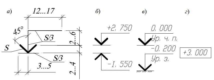
Rice. 4. Applying level marks on views:
a – dimensions of the level mark; b – examples of location and design
level signs on sections and sections; c – the same, with explanatory inscriptions;
d – example of a level sign on the plans
The marking sign may be accompanied by explanatory inscriptions: Ur.ch.p. – finished floor level; Ur.z. - ground level.
Marks on the plans are made in rectangles (Fig. 4, d). Marks above zero level are indicated with a plus sign (for example, + 2.700), below zero - with a minus sign (for example, – 0.200).
The following are accepted in the construction drawings: names types of buildings.
IN names of plans of the building, the level of the finished floor of the floor, the floor number or the designation of the corresponding plane is indicated; when executing a part of the plan - the axes limiting this part, for example:
Plan at elevation +3,000;
2nd floor plan;
Plan 3–3;
Plan at elevation 0.000 in axes 21–39, A–D.
IN names of sections building, the designation of the corresponding cutting plane is indicated (in Arabic numerals), for example, Section 1–1.
IN names of facades building, the extreme axes between which the façade is located are indicated, for example:
Façade 1–5;
Façade 12–1;
Façade A–G.
For multilayer structures callouts, located on shelves in a straight line,
ending with an arrow (Fig. 5). The sequence of inscriptions (material or design of layers indicating their thickness) for individual layers must correspond to the sequence of their location in the drawing from top to bottom and from left to right.
On leader lines, ending with a shelf, additional explanations to the drawing or item numbers of elements in the specification are placed.

Rice. 5. Examples of callouts
Graphic symbols materials in sections and sections of buildings and structures are given in the appendix. 3. The distance between parallel hatching lines is selected within 1 ... 10 mm depending on the hatching area and image scale. Material designations are not used in drawings if the material is homogeneous, if the dimensions of the image do not allow drawing symbol.
Conditional graphic images elements of the building and sanitary installations are given in the appendix. 4.


