To ensure normal air exchange in a house or apartment, two components are necessary: fresh air flow through living rooms and its outflow from technical ones. Ventilation in the bathroom and toilet is one of the components of outflow. Therefore, it is necessary to do it correctly.
According to the principle of operation, ventilation can be natural or mechanical, they also say forced. The natural movement of air occurs due to the movement of wind, temperature differences and resulting pressure differences. When using mechanical ventilation, air movement is caused by fans.
From the point of view of a city person, forced movement is preferable: everyone has long been accustomed to the fact that life support depends on the availability of electricity. And it rarely disappears in cities. But in rural areas in winter, power outages are rather the norm. That’s probably why they mainly strive to make systems non-volatile or, at least, redundant.
But natural ventilation in the toilet and bathroom should be too big sizes. After all, the lower the speed of air movement through the channel, the larger the cross-section of the air duct is needed to ensure the transfer of the required volumes. No one will argue that when the fan is on, the air moves faster. This is even reflected in SNiP: the speed limit for ventilation systems with natural circulation is up to 1 m 3 / h, for mechanical ones - from 3 to 5 m 3 / h. Therefore, for the same room and conditions, the channel sizes will be different. For example, to transmit a flow of 300 m3/h you will need:

Therefore, few people today make do with natural ventilation. Unless in small houses(up to 100 sq. m.). Even in apartments with ducts leading to the roof, ventilation of bathrooms and toilets is done using fans.
When installing an air movement system, you need to remember the basic principle: in order for everything to work efficiently, it is necessary to ensure the flow of air through the living rooms and its flow into the technical rooms. From there it goes through the ventilation ducts.
Today, air flow has become a problem: by reducing heating costs, we have cut off almost all sources of its supply. We install airtight windows, and insulate the walls through which air flows at least a little with airtight materials. The third source - entrance doors - today almost all of them are made of iron, with a rubber seal. In fact, the only way left is ventilation. But we don’t abuse it at all: it blows out the heat. As a result, the problem of dampness is added to the problems of lack of oxygen in the room: there is no inflow, and the outflow is ineffective. Even forced.

If you want the ventilation to be normal and the walls in the rooms not to get wet, make ventilation holes. There is such an option on metal-plastic windows, and there are separate devices that are mounted anywhere on the wall. They come with adjustable flaps, different forms and sizes, covered with bars on the outside. It is best to install under windows, above or behind radiators. Then they are not visible in the room, and in winter the air coming from the street is heated.
Having ensured the inflow, it is necessary to ensure that it enters the technical premises through the doors. Therefore, there should be gaps under all doors: air will flow through them to other rooms. It is advisable to install a ventilation grill in the bathroom doors and/or also make a gap at least 2 cm from the floor. The same rules apply to other technical rooms: kitchen and toilet. Only when there is movement of air masses will ventilation work.

The doors of technical rooms - kitchen, bathroom, toilet - must have ventilation grates or valve. There are even valves with sound absorption, and the smell when proper organization will never enter other premises
To decide which fan to install on the bathtub with toilet, you need to calculate the required air exchange. The calculation is a whole system, but when installing a fan, the main attention is paid to its characteristics: it provides the required air speed. In order not to get involved in calculations, its performance can only be taken according to average numbers.

Air exchange rate for different rooms. With their help, ventilation in the bathroom and toilet is calculated
As you can see from the table (this is from SNiP), for a bathroom at least 25 m 3 / h should be “pumped” per hour, for a toilet or a combined bathroom the speed should be twice as high - 50 m 3 / h. These are the minimum values. In reality, through three (or two) technical rooms - kitchen, toilet, bathroom - as much air should leave as it enters through the supply ventilation.
The air intake is calculated based on the volume of all residential premises and usually exceeds it by 1.5-2 times and the minimum values indicated in the table are not enough to ensure the required air exchange. Therefore, the performance of fans is taken with at least a double reserve, and for kitchens even more: this way there will be no unpleasant odors in the apartment, as well as dampness and fungi. Therefore, when going for a bathroom fan with a capacity less than 100 m 3 /h, it is better not to buy it.
First of all, you need to decide where you will install the fan: in a duct or on the wall. Accordingly, the type: channel or wall. IN wall options there can also be two types: for installation at the entrance of the ventilation duct - they create more pressure, and for ductless installation - exit directly through the wall to the street. For ductless installations, axial type fans are usually used - they cannot create a pressure of more than 50 Pa, and for this reason they are not installed in ducts.

In addition to the performance that you calculated, another important characteristic is the noise level. The smaller it is, the better. It’s good if the noise level is no more than 35 dB.
Another thing to pay attention to is the level of electrical safety. For use in rooms with high humidity, a protection level of at least IP 44 is required (indicated on the fan housing).

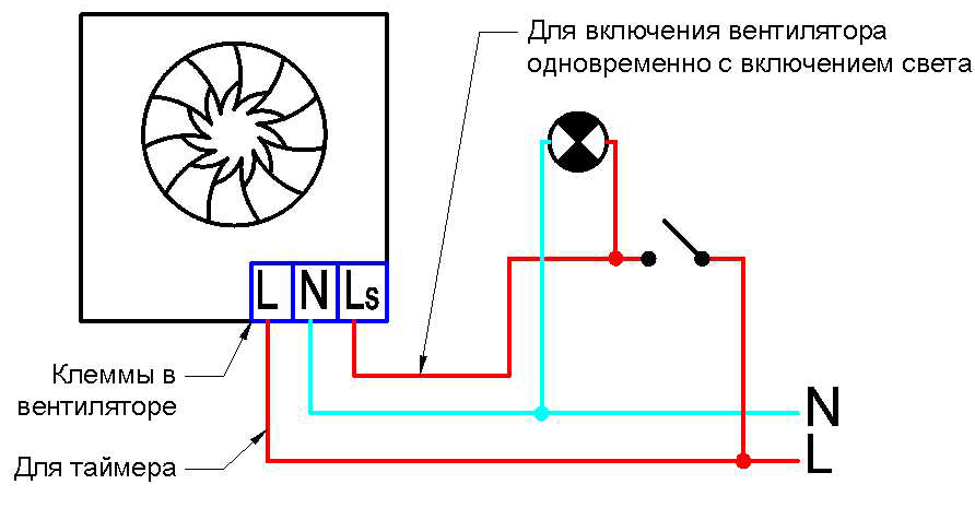
For the fan to operate, a power supply is required, and the main question is how to connect it. There are several possibilities:
The electrical part is the most difficult. You will have to punch a groove in the wall, “pack” the power cable into it, lead it to the installation location of the switch and connect it there, depending on the chosen method.
Installing a fan in the bathroom with your own hands begins after checking the condition of the duct. To do this, remove the grille, if it is not already dismantled, and bring a flame (candle, lighter) or a piece of paper to the hole. If the flame or leaf is steadily pulled towards the channel, the draft is normal. If it either stretches or bends back, the traction is unstable. In this case, if you live in apartment building, odors from neighbors above or below can get to you. Then there may be a smell in the toilet from the ventilation. It is necessary to stabilize the traction.
If the flame or leaf hardly deviates, the channel is clogged or blocked. In this case, mold and dampness, as well as an unpleasant odor, are guaranteed throughout the entire apartment, and in the bathroom, this is a must.

In case of abnormal draft, residents of high-rise buildings clean the channels themselves or call maintenance services. In private houses, in any case, everything falls on the shoulders of the owners. If the channel is unstable, you may have brought it out without taking into account the wind rose and the draft periodically overturns. You can solve the problem by moving the exit, but this is not easy. To begin with, you can try installing a deflector (if you don’t have one) or slightly increasing/decreasing the height.
When installing a fan while it is running, the amount of air exhausted increases significantly. But due to the fact that the housing blocks part of the channel cross-section, at other times, when the fan is not working, the flow decreases three times. As a result, the overall performance of the ventilation system decreases.
To prevent this from happening, you can install a fan with an air intake grille located below and thus increase the performance to normal. The second option is to leave a gap of 1.5-2 cm between the housing and the wall during installation, i.e. make legs. Air will enter the gap and ventilation will be normal in any case. See the video for more details.
Having chosen the installation method and the type of grille, you can proceed directly to installation. Fan sizes may vary. Therefore, each case is individual. But the basic steps are standard:
Here the main difficulties may arise when installing exhaust ducts. When planning, they can be brought together in one place and then brought out onto the roof. This is more difficult from the point of view of internal wiring - you will have to pull the air ducts to the right place, and is also more expensive during construction. But appearance it turns out solid.

Another way to install ventilation ducts: lead it through the wall, and then along external wall lift up. According to the rules, for normal traction at natural ventilation they should rise 50 cm above the ridge. But you will have one common air duct or a separate one for each room - it depends on your desire or on the layout. The picture will look something like this.

There is another option: make a mechanical hood that will work exclusively from the fan. Then, depending on the layout, one of the two options shown in the photo is suitable.

In the first case (on the left), the exhaust hole is made directly at the top of the wall (for air exchange to be effective, it should be located opposite the door, diagonally, at the top). With this device, a regular wall fan is used. The same figure shows how you can reduce the number of required channels. If your bathroom and toilet rooms are located next to each other, through a thin partition, then you can make a hole in the partition and install a grille. In this case, the ventilation of the bath will go through the toilet.
In the second option (pictured on the right) an air duct with duct fan. The solution is simple, but there is one caveat: if the air duct ends under the roof overhang (it is short in the photo, but there are also long ones), then the wood will turn black after some time. If you conclude this from the toilet, this may not happen, but in the case of the bathroom, high humidity will make itself felt in a couple of years. In this case, you can “reach out” the air duct to the edge of the roof or bring it up through the knee (but raise it 50 cm above the roof).
When planning your bathroom design and renovation you should consider one small but very important point- air exchange problem. Good ventilation in the bathroom and toilet is necessary not only to ensure a flow of fresh air.
With the help of this system, they are removed from the bathroom unpleasant odors, and excess humidity. If the ventilation system is planned and implemented correctly, bathroom owners will not have to worry about mold and mildew.
The lack of normal ventilation and the excess humidity caused by this circumstance will create almost luxurious conditions for the development of harmful flora.
Construction manuals clearly indicate the standards that must be followed for effective ventilation of sanitary premises with high humidity.
The system must provide fresh air for the bathroom or toilet at a speed of 25 cubic meters. m/hour, and for a combined unit twice as high - 50 cubic meters. m/hour. These standards are minimum.
Depending on the characteristics of air exchange, natural and forced ventilation are distinguished. In the first case, air exchange occurs due to the difference in air pressure outside and inside the room.
Air flows penetrate through windows, doors, special ventilators, etc. It is worth immediately noting that due to the nature of the bathroom design, the use of natural ventilation does not always achieve the desired effect.
To install ductless ventilation in the bathroom, it is necessary to make an opening that will connect the house ventilation duct with the bathroom room
When forced or artificially ventilating a room, special fans are used to ensure sufficient air exchange.
Most often, a fan helps move air from indoors to outdoors, while fresh air masses enter the bathroom from living quarters.
Sometimes a small fan is placed in the toilet, even with good natural ventilation, to speed up the purification of the air from unpleasant odors.
If it is not possible to naturally organize sufficiently intense air exchange, forced ventilation is mandatory.
Depending on the purpose there are:
The exhaust principle has already been described a little above: air is removed through the ventilation duct, and new air is supplied from the outside. Supply ventilation is organized differently: air is pumped in from the outside and forced out through the channel.
When using mixed ventilation, both the air flow and its removal are regulated.

A beautiful decorative grille for an exhaust hood in a bathroom will not only hide the structure, but can also become an effective detail of a stylish interior.
Experts also distinguish between duct and non-duct ventilation, which is characterized by the presence or absence of a ventilation duct.
Creating dedicated channels should be avoided whenever possible. Usually, an opening is made in the wall that opens into the common ventilation duct of a multi-story building, and a fan is installed in it.
In a separate bathroom, if there is access to the ventilation duct in only one room, another fan is installed in the wall opening between the bathroom and the toilet.
Installing a separate ventilation duct makes sense in places that require intensive removal of polluted or moisture-saturated air.
Before you begin altering the ventilation in the toilet and bathroom, you should carefully study its structure and check its condition. To begin with, they examine the draft: a sheet of paper, a lit match or a lighter is brought to the ventilation hole.
If the paper sticks to the hole, or if the flame is clearly moving towards the ventilation duct, there is a draft. On a hot, windless day, the draft may be significantly less than at other times.
The presence of draft in itself does not always indicate the normal state of the ventilation system.
It is imperative to check the condition of the ventilation duct, which may be partially blocked after inept repair work or for some other reasons.
By removing obstacles, you can significantly improve the quality of the ventilation system.

To check the draft in the bathroom, hold a sheet of paper or the flame of a lighter to the vent. The check should be performed when open door, and then - with closed
If in the latter case the draft has noticeably decreased, you should think about additional means of micro-ventilation.
Most often, it is enough to install special grilles in the doors of the bathroom and toilet to ensure normal flow of fresh air into these rooms even when behind closed doors and windows.
When purchasing a fan, be sure to evaluate the amount of noise it produces. The indicator should not exceed 35 dB. In a bathroom, such equipment should completely renew the air composition approximately 5-8 times within one hour.

Exhaust fans intended for use in bathrooms may have different design and design, in addition, they differ in power
Based on the type of installation, there are ducted household fans designed for installation directly in the ventilation duct, as well as radial models.
They are installed at the exit from the ventilation duct. Typically, channel models look unpresentable, since they are hidden inside the channel, but radial devices are equipped with a beautiful case so as not to spoil the overall impression of the environment.
The design of fans can also vary significantly:
Taking into account the specifics of bathroom ventilation, fans are sometimes additionally equipped with timers, which make it possible to extend the operation of the device in the toilet, or with gyrostats in order to remove air more efficiently. excess moisture from the bathroom.
Fans that are weak in power will not be able to provide normal ventilation of the room, however, you should not use models that are too powerful.
Strong centrifugal fan can cause such an intense flow of air that the influx will not come from outside, but from other ventilation openings, and the exhaust air will again end up in the house.
Interesting information about installing an exhaust fan in a bathroom is presented in the following video:
If for some reason there is no ventilation in the bathroom, creating the necessary system is not so difficult.
Apartment buildings are usually designed in such a way that the ventilation duct is located directly behind the wall of the bathroom or toilet. All that remains is to carefully do it in in the right place hole (if there is none) so that it goes into this channel.
A radial axial fan is installed inside the opening. The device is connected to the power supply, observing all the requirements for the operation of electrical appliances in rooms with high humidity.
If necessary, install additional controls (timer, gyroscope, etc.). The niche is covered with a beautiful decorative grille.
If the apartment has a separate bathroom and the ventilation duct is located behind the walls of both rooms, the second fan is installed in the same way as described above.
Otherwise, the ventilation hole is made in the wall separating the toilet and bathroom. A fan is also placed in this opening and covered with decorative screens on both sides.
Sometimes it is more convenient to use decorative grilles, in which the design provides for mounting the fan in special slots.
The figure clearly shows a diagram of connecting an exhaust fan to the power supply using an i-meter, which allows you to turn off the fan some time after the visitor leaves the bathroom
It is somewhat more difficult to solve the problem of bathroom ventilation when the ventilation duct borders another room. In this case, you will have to create duct ventilation.
First you need to choose a location for the device vent in the bathroom and toilet. Then you need to make a placement plan ventilation duct, along which air masses will move outward.

When creating duct ventilation in a bathroom, a flexible corrugated box is used only for small areas where installation of other structures is impossible or difficult
Distinguish the following types ventilation ducts:
Plastic boxes are easier to install and lighter in weight than metal structures, but they are durable and easy to care for.
Therefore, plastic structures are confidently replacing metal with construction market. Corrugated products are used extremely rarely; they are permissible only for short distances and are used only in particularly difficult cases.
After completing the installation of the ventilation system, it is necessary to check the operation of the equipment.

To create duct ventilation in the bathroom, you should use metal or plastic boxes of rectangular or round cross-section
It happens that the performance of a brand new ventilation system suddenly turns out to be unsatisfactory or is initially ineffective.
This may occur due to one or more errors made during its installation. When figuring out how to properly ventilate a bathroom, you should immediately take these points into account.
Here are a number of flaws that occur most often:
First you need to find out the cause of the problem, then fix it. A number of troubles can be avoided by paying attention to these points at the design stage of the ventilation system.
If this was not done, and problems appeared during the operation of the structure, the entire ventilation system may need to be seriously reworked.
An alternative option to eliminate nuisances is to use different types of sound absorbers to reduce unpleasant sound effects.
To improve the process of moving air masses, you may have to install a more powerful fan.
Sometimes excessive noise when a fan is operating indicates that it is incorrect installation, in which the so-called “alignment” was violated. In this case, it is enough to remove the device and install it again with strict adherence to the installation technology.
Usually after this the amount of noise from the fan operation is significantly reduced.
The supply type of ventilation in bathrooms is used extremely rarely, but if such a decision is made, you should think about the temperature of the air coming from outside.
IN winter time The flow of cold air can cause extremely unpleasant sensations for visitors to the bathroom.
To solve this type of problem, the air entering the room is heated using special electrical appliances.

To ensure a sufficient amount of fresh air enters the bathroom, a beautiful grille is installed at the bottom of the door, which makes the room less airtight
There are several common misconceptions that can negatively affect ventilation work. When designing and installing the system, remember that:
Typically, the design of a ventilation system for a bathroom is very simple; you can do it yourself.
But if some calculations are required or the execution of a ventilation duct of a complex shape is required, and the novice master has no experience in such work, it is better to consult with professionals or completely entrust them with all the work.
The quality of ventilation cannot be neglected, since the health of the residents of the house depends on its condition.
The Aereco ventilation system is a system for organizing indoor air exchange:
– with air flow through passive air supply devices, window or wall (humidity-controlled and manually controlled),
– removing air through ventilation ducts. Exhaust air is removed into the atmosphere either by natural force or by Aereco central fans.
Air flow is regulated by special exhaust grilles (hygro-controlled, with a presence sensor, manually controlled, etc.) installed instead of the standard ones in the bathroom, toilet and kitchen, respectively.
The Aereco ventilation system fully complies with the basic requirements for air exchange in residential premises:
– air flow is carried out into living spaces through air supply devices, window or wall,
– air removal – through exhaust grilles located in the bathroom, toilet and kitchen. Accordingly, the ventilation of the bathroom, toilet and kitchen occurs due to the air coming from the living quarters.
Exhaust grilles, varying in type, characteristics and purpose, are connected via air ducts to the corresponding inlet pipes of the central fan.
To move air indoors, so-called “undercuts” between the floor and the bottom of the door leaf, or flow grilles, must be provided in interior doors.
It should also be noted that Entrance door must be sealed to prevent air from leaking in from the outside.
Basic " driving force» to move air (i.e. to create a vacuum) there are central mechanical fans of different capacities for different volumes of rooms (from 80 to 300 cubic meters per hour), which operate constantly. They have excellent acoustic characteristics and record low energy consumption. The fans are equipped with an electronic control system and a temperature sensor to prevent engine overheating.
Another feature of the Aereco ventilation system is that installation of this system can be carried out at almost any stage of renovation work, since intervention in the interior is minimal.
All inlet devices (hereinafter referred to as valves) of Aereco are passive devices; there are no electric motors. The movement of air through the valve is carried out subject to the functioning of natural or mechanical exhaust. Another main condition for air exchange is the presence of flow between rooms (undercutting the door leaf from below by 1.5 cm, or flow grilles in door leaf or wall).
Supply heating ventilation air(the one we will run through supply valves) is already included in the design of the heating system of almost all residential buildings. If cold air flowed through the cracks in the old windows in the apartment, and the temperature was 20-21 degrees, then replacing the windows with new ones usually leads to an increase in temperature to 25-27 degrees, this is the radiators’ reserve power for heating the ventilation air. Installing Aereco supply valves will return the temperature slightly down by 1-2 degrees, because... the size of the technological hole for the Aereco valve is much smaller than the sum of all the cracks in the old window. The situation is worse if the house is not heated, and with old windows the temperature was only 15-17 degrees. Then, when installing new windows, the temperature will become a comfortable 21-22 degrees and it will be difficult to persuade the client to install a supply valve and lower the temperature somewhat. It turns out that you have to sacrifice fresh air for the sake of warmth, but both are equally important for normal well-being. In this case, it is important to understand that a window is not a heating device; to increase the temperature in the room, you simply need to use additional heat sources.
Ventilation cannot be sacrificed for heating.
If the exhaust system works normally in the apartment, then external cold DRY air flows through the slightly open valve, pushing internal WARM HUMID air away from the valve body and preventing condensation and ice from appearing on the body. If the hood in the apartment does not work, the appearance of frost on the valve body is very likely. The efficiency of the apartment heating system plays a big role; freezing of the valves is affected by the geometry of the window sill (how much it covers the heating radiator), the type and design of the curtains. In office premises in winter, the relative air humidity is lower than in apartments and the likelihood of valves freezing is much lower. In general, statistics on the use of thousands of Aereco window valves in Russian climatic conditions shows that in ordinary apartments without increased moisture release (repair with “wet” processes, an abundance of flowers and wet laundry...) with normal air exchange and heating, the appearance of ice (frost) on the valve body down to -20...25 degrees does not occur. In severe frosts -30...35 degrees, sometimes frost or ice appears on the valve body, which, in principle, does not interfere with the operation of the valves and does not lead to their breakdown. It's still a rare event and you will have to put up with it. In principle, there are no supply window and wall valves that would never freeze under any conditions.
Percentage humidity is the ratio of the actual amount of water in grams per cubic meter of air to the maximum possible amount of water at a given temperature. How is air dehumidified in an apartment? At -20°C and 80% relative humidity, a cubic meter of air contains about 1 gram of water, and at +20°C in a room and 50% relative humidity, a cubic meter of air contains about 9 grams of water. When outside air enters the apartment from the street, it heats up, but the water content in it remains the same and the RELATIVE humidity decreases. For example: a cubic meter of external air with 1g of water mixed with a cubic meter of internal air with 9g of water and heated up to 20°C. It turned out to be 2 cubic meters warm air with a water content of 5 grams per cubic meter. And this already corresponds to approximately 30% relative humidity. Thus, from 50% humidity dropped to 30%.
For information: in winter, in an average Moscow apartment with normal ventilation, the following level of relative humidity is established: at minus 20 degrees - about 18-20%, at minus 10 degrees - about 25%, at 0 degrees - about 30%. No fogging occurs under these conditions double-glazed window and the housing of the air supply device. With normal ventilation!
If we are talking about ventilation with natural air removal, then in the summer, indeed, thermal draft almost disappears and problems with ventilation appear. This is especially noticeable on top floors multi-storey buildings. This is problem. And we don't hide it. But this is not a problem with Aereco air supply units. The solution to this problem is to install a complete Aereco ventilation system with mechanical removal of exhaust air.
Air conditioners in the form of common split systems have nothing to do with ventilation; they drive air from the room back into the room, simultaneously filtering it and cooling (heating). The client is simply breathing cool dirty air rather than warm dirty air. An excess of carbon dioxide and a deficiency of oxygen remain. Experience shows that Aereco valves work well in conjunction with split systems, complementing their temperature control function with an air exchange function.
Yes, indeed, the air quality in our city leaves much to be desired; this is a problem in all large cities. But it would be naive to think that closed, sealed Euro-windows will create a good microclimate in the apartment. On the contrary, the air quality will be even worse, because... The residents themselves are a strong source of air pollution (carbon dioxide, kitchen odors, smoke, sweat, etc.). Only ventilation of premises allows the removal of gaseous products of human activity. To clean the air, you can use various devices for filtering and disinfecting indoor air.
If the windows of the apartment rooms face different sides of the house, then when there is wind, the apartment will blow through. To do this, use air flow restrictors specifically designed by Aereco for such cases.
The valve on the window of such a room is installed as usual, but measures must be taken to ensure unhindered access of air to the balcony. To do this, you must either constantly keep one of the balcony glazing sashes slightly open or make a hole in the balcony glazing frame as for installing the valve, but close it from the inside and outside with standard Aereco canopies.
Contrary to popular belief, the problem is not always associated with insufficient natural ventilation exhaust grille area in the bathroom. But this problem directly depends on the lack of air supply devices in the main premises. In fact, only the air that gets there can be removed from the premises. But insufficient air flow inside residential premises, resulting from a lack of flow between rooms, as well as the use of sealed windows without air supply devices, can lead to inadequate ventilation of wet rooms.
In general, air exchange should be organized as follows: air flow is carried out into living rooms, and exhaust should be organized in the bathroom and kitchen. At the same time, according to paragraph 9.6 of SNiP 31-01-2003 “Residential multi-apartment buildings”: “In residential premises and kitchens, air flow is ensured through adjustable window sashes, transoms, vents, valves or other devices, including autonomous wall air valves with adjustable opening." Thus, when designing an Aereco ventilation system, you should focus on individual characteristics specific object.
Depending on type gas equipment these steps are very different. If your gas stove autonomous, this means that the air for the combustion process comes from outside through a special air duct, and in this case no additional air supply is required in the kitchen. On the other hand, when a gas stove consumes air from the room to maintain the gas combustion process, additional air flow is needed. To check the dimensions of such an air duct and the amount of additional inflow, read the relevant rules.
Depending on type kitchen hood There is different variants:
– the above-slab umbrella filter takes away polluted air from the stove, filters it and returns it to the room. Can be used with natural ventilation systems and centralized mechanical ventilation systems;
– passive exhaust connected to air ducts: only with centralized mechanical ventilation systems.
With natural draft ventilation, there is no risk that smoke will flow back into the room, since when the fireplace is in operation, its chimney produces a significantly greater draft effect compared to standard natural draft ventilation ducts. If there is centralized mechanical ventilation, the automatic device must turn off the centralized ventilation when using the fireplace in order to avoid side draft from the fireplace into the rooms.
For example, for a typical 3-room apartment with a separate bathroom and electric stove, one Aereco fan model VAM767 is enough. With an air flow of 200 m3/h, the consumption will be 44 W/h, i.e. 1.056 kW per day. This is approximately 380 kW per year, which is approximately 900 rubles at the Moscow tariff for a full ventilation system.
For the convenience of our partners, a design department has been created at the Representative Office of Aereko JSC, which will make technical calculations ( design solution) for your customer to equip the facility with an Aereco ventilation system. We do this work for you free of charge.
The efficiency of the design department directly depends on the completeness of the initial data that is necessary for calculations according to your Technical Specifications:
1. Customer information:
- Telephone,
- Fax machine,
– E-mail,
- FULL NAME. contact person,
2. Purpose of the building,
3. Construction area,
4. Explication of premises,
5. Construction drawings:
– floor plans indicating dimensions and elevations relative to ground level;
– BTI plan;
– sections of the building;
– orientation of facades;
- blueprints window profiles(sash, frame, impost).
– 3-4 photographs of the building’s facade, complementing sections of the object on the ground floors, attic floors and roof;
6. Main characteristics of the adopted building structures: – external and interior walls; – window openings; – doors; – floors and coatings;
7. The number of people in each room;
8. Availability of office equipment in each room (for offices);
9. Heating load (calculation of the heating system);
10. Preferences when choosing the type of supply unit - window or wall;
11. Location and characteristics of existing ventilation and air conditioning systems.
P.S. Availability of construction drawings in formats readable by AutoCAD is welcome.
dwg format
The building is designed with supply and exhaust general and local exhaust ventilation with mechanical drive.
Air exchange in the premises is determined to assimilate excess heat from:
Equipment
Solar radiation and compensation for local exhaust.
In air-conditioned areas, outside air is supplied in volume sanitary standards for the worker.
For supporting optimal parameters internal air in the areas of adjustment, processing of parts on CNC machines, an air conditioning system based on split systems and steam humidification is provided supply air during the cold period.
Internal blocks of wall and ceiling types and external blocks installed on facades are connected by freon pipes made of copper pipes with thermal insulation made of foam rubber.
Separate supply ventilation systems for the production building are provided for:
Area for processing parts on CNC machines
- tuning areas of category B3.
Equipment supply systems placed in separate ventilation chambers. The bottom of the holes for receiving devices is located at a height of more than 1 m from the snow cover stability level. Determined according to data from hydrometeorological stations or by calculation, but not lower than 2 m from ground level.
Air exchange in the surface mounting area, ISO cleanliness class 8, is designed for:
-supply of sanitary standards of outdoor air for people;
Air exchanges in clean rooms should not be less than those required for the production of microelectronics in accordance with Table. B2 GOST R ISO 14644-4-2002:
For ISO cleanliness class 8, at least 10 m3 of supplied air per 1 m2 of room area per 1 hour.
Supply air is supplied by a separate system located in the ventilation chamber. Outside air is taken in from an elevation of 16,700m.
To maintain the required microclimate parameters, the supply air is heated and humidified during the cold period, cooled and dried during the warm period.
Supply air is processed in central air conditioners consisting of:
-air filter class F6;
-water air heater;
-air filter class F9;
The coolant is ozone-safe freon, supplied to the air cooler through copper tubes with effective thermal insulation of the “K-FLEX” type.
Supply air is supplied to clean rooms in a volume providing for:
Supply air from the central air conditioner enters the room through air distributors with H11 filters built into the ceiling.
For premises of complex workplaces, a general exchange room is provided supply and exhaust ventilation. Ventilation equipment with a capacity of less than 5000 m3/h is installed in the suspended ceiling of the corridor, the installation of the necessary fire dampers is provided. Outside air is supplied in the amount of sanitary norms to the worker.
To maintain optimal internal air parameters, the areas are equipped with an air conditioning system based on split systems.
Indoor units wall type and external units installed on the facades are connected by freon pipes made of copper pipes with thermal insulation made of foam rubber.
Of people
-equipment
-solar radiation
-supply air
For climate control and dynamic tests General supply and exhaust ventilation is provided.
Air exchange in the premises is determined to assimilate heat emissions from:
Of people
-equipment
-solar radiation
Ventilation equipment is installed in the ventilation chamber. Supply air to the premises is supplied to work area, the exhaust is removed from the upper zone through wall grilles equipped with built-in valves for regulating air flow and direction of the air stream.
The bottom of the openings for receiving devices is located at a height of more than 1 m from the level of snow cover stability, determined according to data from hydrometeorological stations or calculations, but not lower than 2 m from the ground level.
The surveillance cabin is equipped with split air conditioning.
Air exchange in areas of ISO cleanliness class 8 is designed for:
Assimilation of excess heat from technological equipment, people, solar radiation;
- compensation for local exhaust;
-supply of sanitary standards of outdoor air for people; Air exchanges in clean rooms should not be less than those required for the production of microelectronics in accordance with Table. B2 GOST R ISO 14644-4-2002: - for cleanliness class 8 ISO at least 10 m3 of supplied air per 1 m2 of room area per 1 hour. Supply air is supplied by a separate system located in the ventilation chamber. Outside air is taken in from an elevation of 16,700m. To maintain the required microclimate parameters, the supply air is heated and humidified during the cold period, cooled and dried during the warm period.
The supply air is processed in a central air conditioner consisting of:
Receiving unit with air valve;
-air filter class F6;
-water air heater;
- freon air cooler with a separator and a tray for collecting condensate;
-electric air heater for second heating;
-fan unit with reserve section;
-air filter class F9;
-electric humidifier with built-in steam generator;
The source of refrigeration is a compressor-condensing unit installed on the roof of the building.
The coolant is ozone-safe freon, supplied to the air cooler through copper tubes with effective thermal insulation of the “K-FLEX” type.
Supply air is supplied to clean rooms in a volume providing for:
Local compensation exhaust ventilation
- sanitary standards for workers
-compensation for air exfiltrated through door cracks
- creating a pressure difference between clean rooms and the corridor from 5 to 20 Pa.
Supply air from the central air conditioner enters the room through air distributors with H11 filters built into the suspended ceiling.
The exhaust is carried out from the lower zone through wall grilles.
To establish and maintain the pressure difference between the rooms and the corridor, air flow regulators are used on the supply and exhaust air ducts ventilation systems. Excess air flows into the corridors through the cracks of doorways and adjustable grilles installed in the lower part of the premises.
Pressure drops are monitored visually using differential pressure gauges. Local exhaust ventilation systems are provided for process equipment that emits harmful substances.
For exhaust systems with harmful substances For hazard classes 1 and 2, backup fans are provided.
Air ducts of local exhaust ventilation systems running openly through clean rooms are made of stainless polished steel.
The air from the local exhaust ventilation system from the process equipment of the areas is discharged vertically upward, at a height of 2 meters from the roof level.
To ensure optimal parameters of internal air during the warm period, air conditioning based on split systems is provided in the technological bureau and office. Wall-type indoor units and outdoor units installed on facades are connected by freon pipes made of copper pipes with thermal insulation made of foam rubber.
General supply and exhaust ventilation is provided for laboratory premises. Outside air is supplied to the worker in the amount of sanitary norms. To maintain optimal internal air parameters, the laboratories are equipped with an air conditioning system based on split systems.
Ceiling-type indoor units and outdoor units installed on facades are connected by freon pipes made of copper pipes with thermal insulation made of foam rubber.
The cooling capacity of the systems is designed to assimilate excess heat from:
Of people
-equipment
-solar radiation
-supply air
Ventilation equipment is installed in ventilation chambers on technical floor. The air from the local exhaust ventilation system from the process equipment of the areas is discharged vertically upward, at a height of 2 meters from the roof level.
Supply air into the premises is supplied to the work area, exhaust air is removed from the upper zone through wall grilles equipped with built-in valves for regulating air flow and air flow direction.
The supply air for each building is processed in supply air units, which are located in ventilation chambers. Air supply units are arranged:
Receiving unit with air valve;
- EU4 class filter
- water heating heat exchanger
- supply fan
Regulation of the supply air temperature during the cold season is carried out by an automation system based on pump mixing. Automation is provided to regulate the parameters of internal air and to protect heaters from freezing.
The connection of heat exchangers to the heat supply system is provided using two-way valves with the installation of circulation pumps. The necessary air and drain taps, shut-off valves, measuring instruments.
Air ducts of ventilation systems are made of thin-sheet galvanized steel in accordance with GOST 14918-80*.
Air exchanges for all rooms are shown in the tables:
Data on local suctions in tables 1.
Air volumes by hazards in table 2.
Air volume per production premises in table 3.
The room for the GPU is provided with general supply and exhaust ventilation.
Air exchange is determined to assimilate heat emissions from:
Equipment
-solar radiation
The exhaust is provided from the upper zone by two roof fans. The inflow is carried out through an insulated air valve with manual drive type GERMIK-P.
The bottom of the holes for the receiving device is located at a height of more than 1 m from the level of stability of the snow cover, determined according to data from hydrometeorological stations or calculations, but not lower than 2 m from the ground level.
Building No. 1 119600W
Housing No. 2 5000W
Building No. 5 94000W
Building No. 9 95400W
Building No. 11 56500W
Fan units of supply systems are installed in ventilation chambers on vibration-isolating bases in separate blocks with sound-absorbing insulation. Radial ventilation units are connected to air ducts through flexible inserts. In ventilation chambers and heating point foundationless low-noise pumps are installed to supply heaters and heating.
The speed of movement of water in pipelines, air in air ducts and air distributors does not exceed the recommended values for acoustic indicators.


Many programs have been created to help engineers involved in the design and calculation of ventilation. The computer will not only calculate all the required parameters, but also make ventilation drawings. About the most convenient and simple solutions, as well as what the algorithm of their work is based on, read on.
Vent-Calc design software is one of the most functional and accessible. Its operating algorithm is based on Altschul's formulas. Hydraulic calculations of air ducts are made according to a method taken from the Designer's Handbook, edited by Staroverov. Copes equally well with the calculation of natural and forced ventilation.
Program functions for ventilationVent-Calc:
This ventilation calculation program is very good for students just taking a ventilation course at university. Another advantage is that it is free to distribute.

The latest edition of the ventilation design program Vent-Calc allows you to quickly calculate the aerodynamic resistance of the system and other indicators necessary for the preliminary selection of equipment. To do this, the following indicators are required:
Manually such a calculation is quite labor-intensive and is carried out in stages. Therefore, the Vent-Calc calculation program will facilitate and speed up the work of designers and sales specialists climate control technology and qualified installers.

This is a program for designing ventilation, heating, water supply and sewerage systems, and electrical networks. MagiCAD calculates and makes the necessary drawings.
It will be useful for builders, designers, draftsmen and equipment sales managers.
MagiCAD features:
MagiCAD graphics are based on AutoCAD and are actually its addition. The program was created by Finnish developers who simplified its use as much as possible. Therefore, an engineer familiar with AutoCAD can easily understand the subsidiary program for calculating ventilation and other engineering systems MagiCAD. Ease of use is achieved by dividing the core into modules: Ventilation, Piping, Electricity and Room.
The specialist does not need to draw complex air distribution networks, fittings and turns. Ready-made elements are compiled like a constructor. You don't even need a ruler. The main job of the designer is to correctly arrange the existing components to obtain the optimal result. All information about the project is present right there. By looking at the electronic drawing, you can obtain the necessary information about the operation of future ventilation, for example, about the cross-section of air ducts and the speed of air flow in them.
The MagiCAD program for calculating ventilation systems is used by dozens of large design bureaus in Scandinavian countries and many design organizations in the CIS countries.

The GIDRV 3.093 program was created for the calculation of ventilation systems with forced and natural draft. It is a multi-tasking form with a set of tabs: “Scheme characteristics”, “Floors”, “Sections”, “Local resistances”, “Calculation table”.
Functions of the program for calculating natural ventilation GIDRV 3.093:
Having received the results, you can change the initial parameters on any sections of the air ducts and make a new diagram. Using this program for calculating natural ventilation, you can select any combinations, achieving optimal performance work.
Diagrams with explanations (characteristics of channels, system resistance, calculation results) are stored in a single file. Switching and working with various options calculations are very convenient and simple.
Areas with excess pressure are automatically identified and options for solving the problem are provided (narrow the cross-section, use diaphragms, gates, chokes).
The natural ventilation calculation program is equipped with a function for calculating throttling mechanisms, which displays several of the best options and indicates the most suitable one.
During natural ventilation calculations, it detects the most congested areas of the system. Shows the pressure for each section, losses and their causes (pipe resistance, friction).
All calculations can be printed, including tables.
Paid, but a demo version is available for review.

The Fans 400 program was created to calculate smoke ventilation in premises. With its help, you can determine the performance of the smoke removal system from halls, corridors and lobbies. The program for calculating smoke ventilation helps to select the power of fans and other special equipment.
Fans 400 is designed for design engineers, fire inspectors and specialized students.
Using smoke ventilation for calculations will not cause difficulties for a user of any level of training. It is distributed free of charge. For the program to work correctly, you must connect a printer to your computer.
This program for selecting ventilation equipment calculates the diameters of air duct sections. The user enters the maximum values of flow velocity in the air ducts, height differences when calculating natural ventilation or the CMC of the segment. Based on this information, the program selects ventilation equipment of standard diameter in accordance with VSN 353-86 linearly. Thus, the final decision on the diameter remains with the specialist.
If an air duct with non-standard parameters is needed, the program will also help: one parameter is entered, the rest are selected. The selection step is set in the settings.
Indicators of air pressure and temperature are set if the air conditioning system is being calculated. It is possible to obtain data on the pressure at each section by entering its length and total resistance coefficient. The material of the future air duct is taken into account.
You can set one of several options for displaying the dimensions of each area.
Program versions from Ducter 3 and higher for selecting equipment will help you fully calculate the entire ventilation system.

The SVENT program is designed for drawing room ventilation on computers running Windows.
SVENT functions:
Performs 2 types of calculations:
The calculation program works with any types of air ducts (round, rectangular and non-standard shape). You can supplement the air duct database with the necessary samples.
The node base works on the calculation schemes for local resistance coefficients from VSN 353-86, the Designer's Handbook edited by I.G. Staroverov. and several other sources. It can also be supplemented.

This ventilation drawing program is based on the powerful and sophisticated AutoCAD. Along with the development of AutoCAD, CADvent is modified and improved, and new features are added. These are professional ventilation drawing, calculation and presentation programs designed for engineers working in the design and development of ventilation, air conditioning and heating systems.
CADvent functions:
The CADvent program provides the ability to make any changes to a ready-made project, change design parameters, and add new elements. It can be combined with the DIMsilencer programs (a program for selecting a noise suppressor in a ventilation system) and DIMcomfort (selects air distributors, taking into account the flow speed and noise in places where people are located).
Users note ease of use, but there is a lack of Russification, as well as the ability to create an axonometric projection.
Watch the video about another program called Comfort-B.


