Calculation of thin-walled vessels using the momentless theory
Task 1.
The air pressure in the cylinder of the shock-absorbing strut of the aircraft landing gear in the parked position is equal to p = 20 MPa. Cylinder diameter d =….. mm, wall thickness t =4 mm. Determine the main stresses in the cylinder at rest and after takeoff, when the pressure in the shock absorber is ………………….
Answer: (in the parking lot); (after takeoff).
Task 2.
Water enters water turbine by pipeline, outside diameter which for the machine building is equal to .... m, and the wall thickness t =25 mm. The machine building is located 200 m below the level of the lake from which water is drawn. Find the greatest voltage in ……………………….
Answer:
Task 3.
Check the strength of the wall …………………………… with a diameter of ….. m, under operating pressure p = 1 MPa, if the wall thickness t =12 mm, [σ]=100 MPa. Apply IV strength hypothesis.
Answer:
Task 4.
The boiler has a cylindrical diameter d =…. m and is under operating pressure p=….. MPa. Select the thickness of the boiler wall at the permissible stress [σ]=100 MPa, using III strength hypothesis. What would be the required thickness when using IV strength hypotheses?
Answer:
Task 5.
Steel spherical shell diameter d =1 m and thickness t =…. mm is loaded with internal pressure p = 4 MPa. Determine………………tension and………………..diameter.
Answer: mm.
Task 6.
Cylindrical vessel with diameter d =0.8 m has a wall thickness t =... mm. Determine the permissible pressure in the vessel based on IV strength hypothesis if [σ]=…… MPa.
Answer: [p ]=1.5 MPa.
Task 7.
Define ………………………….. material of a cylindrical shell, if, when loaded with internal pressure, the deformations in the direction of the sensors amounted to
Answer: ν=0.25.
Task 8.
Thick duralumin pipemm and inner diametermm reinforced with a thick steel jacket tightly placed on itmm. Find the limit ………………………..for a two-layer pipe according to the yield strength and ……………… stress between the layers at this moment, assuming E st = 200 GPa,E d =70 GPa,
Answer:
Task 9.
Conduit diameter d =…. mm during the launch period had a wall thickness t =8 mm. During operation, due to corrosion, the thickness in places……………………... What is the maximum column of water that a pipeline can withstand with a double safety margin, if the yield strength of the pipe material is
Problem 10.
Gas pipeline diameter d =……. mm and wall thickness t = 8 mm crosses the reservoir at a maximum ………………………….., reaching 60 m. During operation, gas is pumped under pressure p = 2.2 MPa, and during the construction of an underwater crossing there is no pressure in the pipe. What are the highest stresses in a pipeline and when do they occur?
Problem 11.
A thin-walled cylindrical vessel has hemispherical bottoms. What should be the ratio between the thicknesses of the cylindrical and spherical parts so that in the transition zone there is no………………….?
Problem 12.
When manufacturing railway tanks, they are tested under pressure p = 0.6 MPa. Determine ………………………… in the cylindrical part and in the bottom of the tank, taking the test pressure as the calculated one. Calculate according to III strength hypotheses.

Problem 13.
Between two concentrically located bronze pipes a liquid flows under pressure p = 6 MPa. Thickness outer pipe equal toAt what thickness of the inner pipeis provided by …………………….. of both pipes? What are the highest voltages in this case?

Problem 14.
Determine ………………………… of the shell material if, when loaded with internal pressure, the deformation in the direction of the sensors was

Problem 15.
Thin-walled spherical vessel with diameter d =1 m and thickness t =1 cm is under internal pressure and external What is the ………………….. of the vessel P t if
Would the following solution be correct:

Problem 16.
A thin-walled pipe with plugged ends is under the influence of internal pressure p and bending moment M. Using III strength hypothesis, investigate …………………… stressesfrom the value of M for a given r.

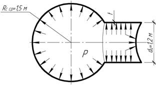
Problem 17.
At what depth are the points with ………………….. meridional and circumferential stresses for the conical vessel shown on the right? Determine the values of these stresses, assuming the specific gravity of the product is equal to γ=…. kN/m 3 .

Problem 18.
The vessel is subjected to gas pressure p = 10 MPa. Find………………………if [σ ]=250 MPa.
Answer: t =30 mm.
Problem 19.
A vertically standing cylindrical tank with a hemispherical bottom is filled to the top with water. Thickness of side walls and bottom t =2 mm. Define ………………………. stresses in the cylindrical and spherical parts of the structure.

Answer:
Problem 20.
A cylindrical reservoir is filled to a depth of H 1 = 6 m with liquid of specific gravityand on top - to a thickness of H 2 = 2 m - with water. Determine …………………….. of the tank at the bottom if [σ ]=60 MPa.

Answer: t =5 mm.
Problem 21.
A small gas holder for lighting gas has wall thickness t =5 mm. Find ……………… of the upper and lower vessels.

Answer:
Problem 22.
The valve float of the testing machine is a closed cylinder made of aluminum alloy with a diameter d =…..mm. The float is subjected to………………………pressure р =23 MPa. Determine the thickness of the float wall using the fourth strength hypothesis, if [σ]=200 MPa.

Answer: t =5 mm.
Problem 23.
Thin-walled spherical vessel with a diameter d =1 m and thickness t =1 cm is under the influence of internal ……………… and external What is the ……………….. of the vessel walls If

Answer: .
Problem 24.
Determine the maximum ………………… and circumferential stresses in a toroidal cylinder if p=…. MPa, t =3 mm, A=0.5 mm; d =0.4 m.

Answer:
Problem 25.
Steel hemispherical vessel of radius R =... m is filled with liquid with a specific gravity γ = 7.5 kN/m 3. Taking ……………………. 2 mm and using III strength hypothesis, determine required thickness vessel walls, if [σ]=80 MPa.

Answer: t =3 mm.
Problem 26.
Determine …………………… the points with the highest meridional and circumferential stresses and calculate these stresses if the wall thickness t =... mm, specific gravity of the liquid γ = 10 kN/m 3.

Answer: at a depth of 2 m; at a depth of 4 m.
Problem 27.
A cylindrical vessel with a conical bottom is filled with liquid with a specific gravity γ = 7 kN/m 3. The wall thickness is constant and equal t =...mm. Define …………………………….. and circumferential stresses.

Answer:
Problem 28.
A cylindrical vessel with a hemispherical bottom is filled with liquid with a specific gravity γ = 10 kN/m 3. The wall thickness is constant and equal t =... mm. Determine the maximum stress in the vessel wall. How many times will this voltage increase if the length………………………………, keeping all other dimensions constant?

Answer: will increase by 1.6 times.
Problem 29.
To store oil with a specific gravity γ = 9.5 kN/m 3, a vessel in the form of a truncated cone with a wall thickness is used t =10 mm. Determine the largest …………………………. stress in the vessel wall.

Answer:
Problem 30.
The thin-walled conical bell is located under a layer of water. Determine …………………………….. and hoop stresses if air pressure on the surface under the bell wall thickness t = 10 mm.

Answer:
Problem 31.
Shell thickness t =20 mm, shaped like an ellipsoid of rotation (Ox – axis of rotation), loaded with internal pressure р=…. MPa. Find ………………….. in longitudinal and transverse sections.

Answer:
Problem 32.
Using the third strength hypothesis, check the strength of a vessel shaped like a paraboloid of revolution with a wall thickness t =... mm, if the specific gravity of the liquid is γ = 10 kN/m 3, the permissible stress [σ] = 20 MPa, d = h =5 m. Check strength by height……………………………...

Answer: those. strength is guaranteed.
Problem 33.
A cylindrical vessel with spherical bottoms is designed to store gas under pressure p =... MPa. Under …………………, will it be possible to store gas in a spherical vessel of the same capacity with the same material and wall thickness? What kind of material savings does this achieve?

Answer: savings will be 36%.
Problem 34.
Cylindrical shell with wall thickness t =5 mm compressed by force F =….. kN. Due to manufacturing inaccuracies, the forming shells received little…………………………. Neglecting the influence of this curvature on the meridional stresses, calculatein the middle of the height of the shell, assuming that the generators are curved along one half-wave of the sinusoid, and f =0.01 l; l= r.

Answer:
Problem 35.
A vertical cylindrical vessel is designed to store liquid volume V And specific gravityγ. The total thickness of the upper and lower bases, assigned for design reasons, is equal toDetermine the most favorable height of the tank H opt, at which the mass of the structure will be minimal.Taking the height of the tank equal to H opt, find ………………………….. parts, assuming [σ]=180 MPa, Δ=9 mm, γ=10 kN/m 3, V =1000 m 3.

Answer: N opt =9 m, mm.
Problem 36.
Long thin tube thick t =…. mm is placed with a tightness Δ on an absolutely rigid rod of diameter d =…..mm . …………… must be applied to the tube to remove it from the rod if Δ=0.0213 mm; f =0.1; l=10 cm, E=100 GPa, ν=0.35.

Answer: F =10 kN.
Problem 37.
A thin-walled cylindrical vessel with spherical bottoms is subjected from the inside to gas pressure p = 7 MPa. By ……………………………….. diameter E 1 =E 2 =200 GPa.

Answer: N 02 =215 N.
Problem 38.
Among others structural elements Cylinders are used in aviation and rocketry high pressure. They usually have a cylindrical or spherical shape and for them, as for other structural units, it is extremely important to comply with the minimum weight requirement. The design of the shaped cylinder shown in the figure is proposed. The walls of the cylinder consist of several cylindrical sections connected by radial walls. Since the cylindrical walls have a small radius, the stress in them is reduced, and it can be hoped that despite the increase in weight due to the radial walls, the total weight of the structure will be less than for an ordinary cylinder having the same volume……………………… …….?

Problem 39.
Determine ……………………… of a thin-walled shell of equal resistance containing liquid of specific gravity γ.

Task 1.
What is the pressure (internal or external)……………………. pipes? How many times are the greatest equivalent stresses according to III hypothesis of strength in one case more or less than in the other if the pressure values are the same? Will the largest radial displacements be equal in both cases?
Task 2.
The two pipes differ only in size cross section: 1st pipe – A=20 cm, b =30 cm; 2nd pipe – A=10 cm, b =15 cm. Which of the pipes has ……………………… ability?
Task 3.
Thick wall pipe with dimensions A=20 cm and b =40 cm cannot withstand the set pressure. In order to increase the load-bearing capacity, two options are offered: 1) increase the outer radius by P times b ; 2) reduce the internal radius by P times A. Which option gives ……………………………. at same value P?
Task 4.
Pipe with dimensions A=10 cm and b =20 cm withstands pressure p=….. MPa. How much (in percent) ……………….. is the load-bearing capacity of the pipe if the outer radius is increased by … times?
Task 5.
At the end of the First World War (1918), Germany manufactured an ultra-long-range cannon for shelling Paris from a distance of 115 km. It was steel pipe 34 m long and 40 cm thick at the breech. The gun weighed 7.5 MN. Its 120-kilogram projectiles were a meter long with a diameter of 21 cm. The charge used 150 kg of gunpowder, which developed a pressure of 500 MPa, which ejected the projectile with initial speed 2 km/s. What should be the ……………………………. used to make a gun barrel, if not less than one and a half times the safety margin?
In technology, there are often vessels whose walls perceive the pressure of liquids, gases and granular bodies ( steam boilers, tanks, working chambers of engines, tanks, etc.). If the vessels have the shape of bodies of revolution and their wall thickness is insignificant, and the load is axisymmetric, then determining the stresses arising in their walls under load is very simple.
In such cases, without a large error, it can be assumed that only normal stresses (tensile or compressive) arise in the walls and that these stresses are distributed evenly throughout the wall thickness.
Calculations based on such assumptions are well confirmed by experiments if the wall thickness does not exceed approximately the minimum radius of curvature of the wall.
Let's cut out an element with dimensions and from the wall of the vessel.
We denote the wall thickness t(Fig. 8.1). Radius of curvature of the vessel surface at a given location and Load on the element - internal pressure , normal to the surface of the element.

Let us replace the interaction of the element with the remaining part of the vessel with internal forces, the intensity of which is equal to and . Since the wall thickness is insignificant, as already noted, these stresses can be considered evenly distributed throughout the wall thickness.
Let's create a condition for the equilibrium of the element, for which we will project the forces acting on the element onto the direction of the normal pp to the surface of the element. The load projection is equal to  .
The projection of stress onto the normal direction will be represented by a segment ab, equal
.
The projection of stress onto the normal direction will be represented by a segment ab, equal  Projection of force acting on edge 1-4 (and 2-3) ,
equal to
Projection of force acting on edge 1-4 (and 2-3) ,
equal to  . Similarly, the projection of the force acting on edge 1-2 (and 4-3) is equal to
  .
.
By projecting all the forces applied to the selected element onto the normal direction pp, we get
Due to the small size of the element, it can be taken

Taking this into account, from the equilibrium equation we obtain
Considering that d  And
And
 we have

Reduced by  and dividing by t, we get
 (8.1)
(8.1)
This formula is called Laplace's formula. Let's consider the calculation of two types of vessels that are often found in practice: spherical and cylindrical. In this case, we will limit ourselves to cases of internal gas pressure.

| a) b) |
1. Spherical vessel. In this case  And
And  From (8.1) it follows
  where
where
 (8.2)
(8.2)
Since in in this case If there is a plane stress state, then to calculate the strength it is necessary to apply one or another strength theory. The principal stresses have the following values: According to the third strength hypothesis;  . Substituting
  And
And  , we get
 (8.3)
(8.3)
i.e., strength testing is carried out as in the case of a uniaxial stress state.
According to the fourth strength hypothesis,  . Since in this case
  , That
 (8.4)
(8.4)
i.e., the same condition as under the third strength hypothesis.
2. Cylindrical vessel. In this case  (cylinder radius) and
  (radius of curvature of the cylinder generatrix).
From Laplace's equation we obtain  where
where
 (8.5)
(8.5)
To determine the stress, let’s cut the vessel with a plane perpendicular to its axis and consider the equilibrium condition of one of the parts of the vessel (Fig. 47 b).
Projecting onto the axis of the vessel all the forces acting on the cut-off part, we obtain
 (8.6)
(8.6)
Where  -
the resultant of the gas pressure forces at the bottom of the vessel.
-
the resultant of the gas pressure forces at the bottom of the vessel.
Thus,  ,
where
,
where
 (8.7)
(8.7)
Note that due to the thin-walledness of the ring, which is a cross-section of a cylinder along which stresses act, its area is calculated as the product of the circumference and the wall thickness. Comparing in a cylindrical vessel, we see that
In engineering practice, structures such as tanks, water reservoirs, gas tanks, air and gas cylinders, building domes, chemical engineering apparatus, parts of turbine and jet engine housings, etc. are widely used. All these structures, from the point of view of their strength and rigidity calculations, can be classified as thin-walled vessels (shells) (Fig. 13.1, a).
A characteristic feature of most thin-walled vessels is that in shape they represent bodies of rotation, i.e. their surface can be formed by rotating some curve  around the axis ABOUT-ABOUT. Section of a vessel by a plane containing an axis ABOUT-ABOUT, called meridional section, and sections perpendicular to meridional sections are called district. Circumferential sections, as a rule, have the shape of a cone. The lower part of the vessel shown in Fig. 13.1b is separated from the upper by a circumferential section. The surface dividing the thickness of the walls of the vessel in half is called middle surface. A shell is considered to be thin-walled if the ratio of the smallest principal radius of curvature at a given point on the surface to the thickness of the shell wall exceeds 10
  .
.
Let us consider the general case of the action of some axisymmetric load on the shell, i.e. such a load that does not change in the circumferential direction and can only change along the meridian. Let us select an element from the shell body with two circumferential and two meridional sections (Fig. 13.1, a). The element experiences tension in mutually perpendicular directions and bends. Bilateral tension of an element corresponds to a uniform distribution of normal stresses across the wall thickness  and the occurrence of normal forces in the shell wall. A change in the curvature of the element suggests the presence of bending moments in the shell wall. When bending, normal stresses arise in the beam wall, varying along the wall thickness.
Under the action of an axisymmetric load, the influence of bending moments can be neglected, since normal forces are predominant. This occurs when the shape of the shell walls and the load on it are such that a balance between external and internal forces is possible without the appearance of bending moments. The theory for calculating shells, based on the assumption that the normal stresses arising in the shell are constant over the thickness and, therefore, there is no bending of the shell, is called momentless theory of shells. The momentless theory works well if the shell does not have sharp transitions and hard pinches and, moreover, is not loaded with concentrated forces and moments. In addition, this theory gives more accurate results the smaller the thickness of the shell wall, i.e. the closer to the truth the assumption of a uniform distribution of stresses throughout the wall thickness.
In the presence of concentrated forces and moments, sharp transitions and pinching, solving the problem becomes much more complicated. In places where the shell is attached and in places of sudden changes in shape, increased stresses arise due to the influence of bending moments. In this case, the so-called moment theory of shell calculation. It should be noted that issues of the general theory of shells go far beyond the strength of materials and are studied in special sections of structural mechanics. In this manual, when calculating thin-walled vessels, the momentless theory is considered for cases when the problem of determining the stresses acting in the meridional and circumferential sections turns out to be statically determinable.
13.2. Determination of stresses in symmetrical shells using the momentless theory. Derivation of Laplace's equation
Let us consider an axisymmetric thin-walled shell experiencing internal pressure from the weight of the liquid (Fig. 13.1, a). Using two meridional and two circumferential sections, we select an infinitesimal element from the shell wall and consider its equilibrium (Fig. 13.2).

In meridional and circumferential sections there are no tangential stresses due to the symmetry of the load and the absence of mutual displacements of the sections. Consequently, only the main normal stresses will act on the selected element: meridional stress  And hoop stress
 . Based on the momentless theory, we will assume that along the wall thickness the stress
  And
And  distributed evenly. In addition, we will refer all dimensions of the shell to the middle surface of its walls.
The middle surface of the shell is a surface of double curvature. Let us denote the radius of curvature of the meridian at the point under consideration  , the radius of curvature of the middle surface in the circumferential direction is denoted by
  . Forces act along the edges of the element
  And
And  . On inner surface the selected element is subject to fluid pressure
  , whose resultant is equal to
  . Let us project the above forces onto the normal
  to the surface:
Let us depict the projection of the element onto the meridional plane (Fig. 13.3) and, based on this figure, write the first term in expression (a). The second term is written by analogy.
Replacing the sine in (a) with its argument due to the smallness of the angle and dividing all terms of equation (a) by  , we get:
 (b).
(b).
Considering that the curvatures of the meridional and circumferential sections of the element are equal, respectively  And
And  , and substituting these expressions into (b) we find:
 .
(13.1)
.
(13.1)
Expression (13.1) represents the equations of Laplace, named after the French scientist who obtained it at the beginning of the 19th century while studying surface tension in liquids.

Equation (13.1) includes two unknown voltages  And
And  . Meridional stress
  we will find by composing the equilibrium equation for the axis
  forces acting on the cut-off part of the shell (Fig. 12.1, b). The circumferential area of the shell walls is calculated using the formula
  . Voltages
  due to the symmetry of the shell itself and the load relative to the axis
  distributed evenly over the area. Hence,
 ,
(13.2)
,
(13.2)
Where  - the weight of the part of the vessel and liquid lying below the section under consideration;
  fluid pressure, according to Pascal’s law, is equal in all directions and equal
  , Where
  depth of the section under consideration, and
  - weight per unit volume of liquid. If a liquid is stored in a vessel under some excess pressure compared to atmospheric
  , then in this case
  .
.
Now knowing the tension  from the Laplace equation (13.1) one can find the voltage
  .
.
When solving practical problems, due to the fact that the shell is thin, instead of the radii of the middle surface  And
And  substitute the radii of the outer and inner surfaces.
As already noted, circumferential and meridional stresses  And
And  are the main stresses. As for the third principal stress, the direction of which is normal to the surface of the vessel, then on one of the surfaces of the shell (external or internal, depending on which side the pressure acts on the shell) it is equal to
  , and on the opposite – zero. In thin-walled shells, stress
  And
And  always much more
  . This means that the magnitude of the third principal stress can be neglected compared to
  And
And  , i.e. consider it equal to zero.
Thus, we will assume that the shell material is in a plane stressed state. In this case, to assess the strength depending on the state of the material, the appropriate strength theory should be used. For example, using the fourth (energy) theory, we write the strength condition in the form:
Let's consider several examples of calculations of momentless shells.
Example 13.1. A spherical vessel is under the influence of uniform internal gas pressure  (Fig.13.4). Determine the stresses acting in the wall of the vessel and evaluate the strength of the vessel using the third theory of strength. We neglect the own weight of the walls of the vessel and the weight of the gas.

1. Due to the circular symmetry of the shell and the axisymmetric stress load  And
And  are the same at all points of the shell. Assuming in (13.1)
  ,
, , A
, A  , we get:
 .
(13.4)
.
(13.4)
2. We check according to the third theory of strength:
 .
.
Considering that  ,
, ,
, , the strength condition takes the form:
 .
(13.5)
.
(13.5)
Example 13.2. The cylindrical shell is under the influence of uniform internal gas pressure  (Fig. 13.5). Determine the circumferential and meridional stresses acting in the wall of the vessel and evaluate its strength using the fourth theory of strength. Neglect the self-weight of the vessel walls and the weight of the gas.

1. Meridians in the cylindrical part of the shell are generatrices for which  . From Laplace’s equation (13.1) we find the circumferential stress:
 .
(13.6)
.
(13.6)
2. Using formula (13.2), we find the meridional stress, assuming  And
And  :
:
 .
(13.7)
.
(13.7)
3. To assess strength, we accept:  ;
; ;
; . The strength condition according to the fourth theory has the form (13.3). Substituting expressions for circumferential and meridional stresses (a) and (b) into this condition, we obtain
Example 12.3. A cylindrical tank with a conical bottom is under the influence of the weight of the liquid (Fig. 13.6, b). Establish the laws of changes in circumferential and meridional stresses within the conical and cylindrical part of the tank, find the maximum stresses  And
And  and construct diagrams of stress distribution along the height of the tank. Neglect the weight of the tank walls.

1. Find the fluid pressure at depth  :
:
 . (A)
. (A)
2. We determine the circumferential stresses from the Laplace equation, taking into account that the radius of curvature of the meridians (generators)  :
:
 . (b)
. (b)
For the conical part of the shell
 ;
; . (V)
. (V)
Substituting (c) into (b) we obtain the law of change in circumferential stresses within the conical part of the tank:
 .
(13.9)
.
(13.9)
For the cylindrical part, where  the distribution law of circumferential stresses has the form:
 .
(13.10)
.
(13.10)

Diagram  shown in Fig. 13.6, a. For the conical part, this diagram is parabolic. Its mathematical maximum occurs in the middle of the total height at
  . At
. At  it has a conditional meaning when
  the maximum stress falls within the conical part and has a real value:
 .
(13.11)
.
(13.11)
3. Determine meridional stresses  . For a conical part, the weight of the liquid in the volume of a cone with a height
  is equal to:
 . (G)
. (G)
Substituting (a), (c) and (d) into the formula for meridional stresses (13.2), we obtain:
 .
(13.12)
.
(13.12)
Diagram  shown in Fig. 13.6, c. Plot maximum
  , outlined for the conical part also along a parabola, occurs when
  . It has real significance when
  , when it falls within the conical part. The maximum meridional stresses are equal to:
 .
(13.13)
.
(13.13)
In the cylindrical part the voltage  does not change in height and is equal to the voltage at the upper edge at the place where the tank is suspended:
 .
(13.14)
.
(13.14)
In places where the surface of the tank has a sharp break, such as, for example, at the point of transition from a cylindrical part to a conical part (Fig. 13.7) (Fig. 13.5), the radial component of the meridional stresses  not balanced (Fig. 13.7).

This component along the perimeter of the ring creates a radial distributed load with an intensity  , tending to bend the edges of the cylindrical shell inward. To eliminate this bend, a stiffener (spacer ring) is installed in the form of an angle or channel that encircles the shell at the fracture site. This ring carries radial load
  (Fig. 13.8, a).
Let us cut out a part of it from the spacer ring using two infinitely closely spaced radial sections (Fig. 13.8b) and determine the internal forces that arise in it. Due to the symmetry of the spacer ring itself and the load distributed along its contour, shear force and bending moment in the ring do not occur. Only the longitudinal force remains  . Let's find her.

Let us compile the sum of the projections of all forces acting on the cut out element of the spacer ring onto the axis  :
:
 . (A)
. (A)
Let's replace the sine of the angle  angle due to its smallness
  and substitute in (a). We get:
 ,
,
 (13.15)
Thus, the spacer ring works in compression. The strength condition takes the form:
 ,
(13.16)
,
(13.16)
Where  radius of the midline of the ring;
  - cross-sectional area of the ring.
Sometimes, instead of a spacer ring, a local thickening of the shell is created by bending the edges of the bottom of the tank into the shell.
If the shell experiences external pressure, then the meridional stresses will be compressive and the radial force  will become negative, i.e. directed outward. Then the stiffening ring will work not in compression, but in tension. In this case, the strength condition (13.16) will remain the same.
It should be noted that installing a stiffening ring does not completely eliminate the bending of the shell walls, since the stiffening ring constrains the expansion of the shell rings adjacent to the rib. As a result, the forming shells near the stiffening ring are bent. This phenomenon is called the edge effect. It can lead to a significant local increase in stress in the shell wall. The general theory of taking into account the edge effect is discussed in special courses using the moment theory of calculating shells.
Online assistance by appointment only
Problem 1
Determine the difference in piezometer levels h.
The system is in equilibrium.
The piston area ratio is 3. H= 0.9 m.
Liquid water.
Problem 1.3
Determine the level difference h in piezometers when the multiplier pistons are in equilibrium, if D/d = 5, H= 3.3 m. Build a graph h = f(D/d), If D/d= 1.5 ÷ 5.
Problem 1. 5
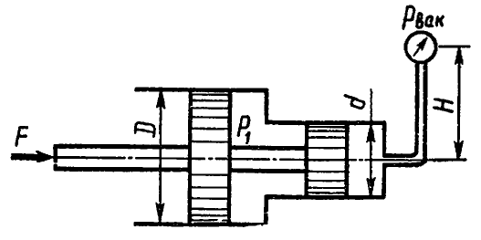
A thin-walled vessel consisting of two cylinders with diameters d= 100 mm and D= 500 mm, the lower open end is lowered below the water level in tank A and rests on supports C located at a height b= 0.5 m above this level.
Determine the magnitude of the force perceived by the supports if a vacuum is created in the vessel, causing the water in it to rise to a height a + b= 0.7 m. Own weight of the vessel G= 300 N. How does a change in diameter affect the result? d?

Problem 1.7
Define absolute pressure air in the vessel, if the reading of the mercury device h= 368 mm, height H= 1 m. Density of mercury ρ rt = 13600 kg/m 3. Atmosphere pressure p atm = 736 mm Hg. Art.

Problem 1.9
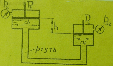
Determine the pressure above the piston p 01, if known: forces on the pistons P 1 = 210 N, P 2 = 50 N; instrument reading p 02 = 245.25 kPa; piston diameters d 1 = 100 mm, d 2 = 50 mm and height difference h= 0.3 m. ρ Hg /ρ = 13.6.
Problem 1.16
Determine pressure p in the hydraulic system and load weight G lying on the piston 2 , if to lift it to the piston 1 force applied F= 1 kN. Piston diameters: D= 300 mm, d= 80 mm, h= 1 m, ρ = 810 kg/m3. Build a graph p = f(D), If D varies from 300 to 100 mm.

Problem 1.17.
Define maximum height N max , to which gasoline can be sucked in with a piston pump if its pressure saturated vapors amounts to h n.p. = 200 mmHg Art., and atmospheric pressure h a = 700 mm Hg. Art. What is the force along the rod if N 0 = 1 m, ρ b = 700 kg/m 3 ; D= 50 mm?
Build a graph F = ƒ( D) when it changes D from 50 mm to 150 mm.

Problem 1.18
Determine diameter D 1 hydraulic cylinder required to lift the valve when there is excess fluid pressure p= 1 MPa, if the pipeline diameter D 2 = 1 m and mass of moving parts of the device m= 204 kg. When calculating the friction coefficient of the valve in the guide surfaces, take f= 0.3, the friction force in the cylinder is considered equal to 5% of the weight of the moving parts. The pressure behind the valve is equal to atmospheric pressure; neglect the influence of the stem area.
Build a dependency graph D 1 = f(p), If p varies from 0.8 to 5 MPa.

Problem 1.19
When the hydraulic accumulator is charged, the pump supplies water to cylinder A, lifting plunger B along with the load upward. When the battery is discharged, the plunger, sliding down, squeezes water out of the cylinder under the influence of gravity into hydraulic presses.
1. Determine the water pressure when charging p z (developed by the pump) and discharge p p (obtained by the presses) of the battery, if the mass of the plunger together with the load m= 104 t and plunger diameter D= 400 mm.
The plunger is sealed with a cuff, the height of which b= 40 mm and coefficient of friction on the plunger f = 0,1.
Build a graph p z = f(D) And p p = f(D), If D varies from 400 to 100 mm, the mass of the plunger with the load is considered unchanged.

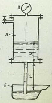
Problem 1.21
In a sealed container A there is molten babbitt (ρ = 8000 kg/m3). When the vacuum gauge shows p vac = 0.07 MPa filling the ladle B stopped. Wherein H= 750 mm. Determine the height of the babbitt level h in the feeder vessel A.
Problem 1.23
Define strength F necessary to keep the piston at a height h 2 = 2 m above the surface of the water in the well. A column of water rises above the piston as high as h 1 = 3 m. Diameters: piston D= 100 mm, rod d= 30 mm. Ignore the weight of the piston and rod.

Problem 1.24
The vessel contains molten lead (ρ = 11 g/cm3). Determine the pressure force acting on the bottom of the vessel if the height of the lead level is h= 500 mm, vessel diameter D= 400 mm, pressure and vacuum gauge reading p vac = 30 kPa.
Construct a graph of the pressure force versus the diameter of the vessel if D varies from 400 to 1000 mm

Problem 1.25
Determine pressure p 1 fluid that must be supplied to the hydraulic cylinder to overcome the force directed along the rod F= 1 kN. Diameters: cylinder D= 50 mm, rod d= 25 mm. Tank pressure p 0 = 50 kPa, height H 0 = 5 m. Ignore friction force. Liquid density ρ = 10 3 kg/m 3.

Problem 1.28
The system is in equilibrium. D= 100 mm; d= 40 mm; h= 0.5 m.
What force must be applied to pistons A and B if a force acts on piston C P 1 = 0.5 kN? Ignore friction. Build a dependency graph P 2 from diameter d, which varies from 40 to 90 mm.

Problem 1.31
Define strength F on the spool rod if the vacuum gauge reading p vac = 60 kPa, overpressure p 1 = 1 MPa, height H= 3 m, piston diameters D= 20 mm and d= 15 mm, ρ = 1000 kg/m 3.
Build a graph F = f(D), If D varies from 20 to 160 mm.
Problem 1.32
A system of two pistons connected by a rod is in equilibrium. Define strength F, compressing the spring. The liquid located between the pistons and in the tank is oil with a density ρ = 870 kg/m 3. Diameters: D= 80 mm; d= 30 mm; height N= 1000 mm; overpressure R 0 = 10 kPa.

Problem 1.35
Define load P on the cover bolts A And B hydraulic cylinder diameter D= 160 mm, if to a plunger with a diameter d= 120 mm force applied F= 20 kN.
Build a dependency graph P = f(d), If d varies from 120 to 50 mm.

Task1.37
The figure shows the design diagram of a hydraulic lock, the flow section of which opens when fed into the cavity A control fluid flow with pressure p y. Determine at what minimum value p y piston pusher 1 will be able to open the ball valve if the spring preload is known 2 F= 50 H; D = 25 mm, d = 15 mm, p 1 = 0.5 MPa, p 2 = 0.2 MPa. Neglect frictional forces.

Problem 1.38
Determine gauge pressure p m, if the force on the piston P= 100 kgf; h 1 = 30 cm; h 2 = 60 cm; piston diameters d 1 = 100 mm; d 2 = 400 mm; d 3 = 200 mm; ρ m /ρ in = 0.9. Define p m.

Problem 1.41
Determine the minimum force value F, applied to the rod, under the influence of which a piston with a diameter of D= 80 mm, if the spring force pressing the valve to the seat is equal to F 0 = 100 H, and fluid pressure p 2 = 0.2 MPa. Valve inlet diameter (seat) d 1 = 10 mm. Rod diameter d 2 = 40 mm, fluid pressure in the rod cavity of the hydraulic cylinder p 1 = 1.0 MPa.

Problem 1.42
Determine the amount of preload of the differential spring safety valve(mm), ensuring that the valve begins to open at p n = 0.8 MPa. Valve diameters: D= 24 mm, d= 18 mm; spring stiffness With= 6 N/mm. The pressure to the right of the larger and to the left of the small pistons is atmospheric.
Problem 1.44
In a hydraulic jack with manual drive(Fig. 27) at the end of the lever 2 force applied N= 150 N. Pressure diameters 1 and lifting 4 plungers are respectively equal: d= 10 mm and D= 110 mm. Small lever arm With= 25 mm.
Taking into account the general efficiency of the hydraulic jack η = 0.82, determine the length l lever 2 sufficient to lift the load 3 weighing 225 kN.
Build a dependency graph l = f(d), If d varies from 10 to 50 mm.

Task 1.4 5
Determine height h column of water in a piezometric tube. A column of water balances a full piston with D= 0.6 m and d= 0.2 m, having a height H= 0.2 m. Neglect the self-weight of the piston and friction in the seal.
Build a graph h = f(D), if the diameter D varies from 0.6 to 1 m.

Problem 1.51
Determine the diameter of the piston = 80.0 kg; depth of water in cylinders H= 20 cm, h= 10 cm.
Build dependency P = f(D), If P= (20...80) kg.

Problem 1.81
Determine the reading of a two-fluid pressure gauge h 2, if the pressure on the free surface in the tank p 0 abs = 147.15 kPa, water depth in the tank H= 1.5 m, distance to mercury h 1 = 0.5 m, ρ rt / ρ in = 13.6.

Problem 2.33
Air is sucked in by the engine from the atmosphere, passes through the air cleaner and then through a pipe with a diameter of d 1 = 50 mm supplied to the carburetor. Air density ρ = 1.28 kg/m3. Determine the vacuum in the diffuser neck with diameter d 2 = 25 mm (section 2–2) at air flow Q= 0.05 m 3 /s. Accept the following resistance coefficients: air cleaner ζ 1 = 5; knees ζ 2 = 1; air damper ζ 3 = 0.5 (related to the speed in the pipe); nozzle ζ 4 = 0.05 (related to the velocity at the diffuser neck).

Problem 18
To weigh heavy loads 3 weighing from 20 to 60 tons, a hydrodynamometer is used (Fig. 7). Piston 1 diameter D= 300 mm, rod 2 diameter d= 50 mm.
Neglecting the weight of the piston and rod, construct a graph of pressure readings R pressure gauge 4 depending on weight m cargo 3.
Problem 23
In Fig. Figure 12 shows a diagram of a hydraulic valve with a spool diameter d= 20 mm.
Neglecting friction in the hydraulic valve and the weight of spool 1, determine the minimum force that the compressed spring 2 must develop to balance the oil pressure in the lower cavity A R= 10 MPa.
Draw a graph of spring force versus diameter d, If d varies from 20 to 40 mm.

Problem 25
In Fig. Figure 14 shows a diagram of a hydraulic distributor with a flat valve of 2 diameters d= 20 mm. In the pressure cavity IN hydraulic valve operates oil pressure p= 5 MPa.
Neglecting back pressure in the cavity A hydraulic distributor and the force of a weak spring 3, determine the length l lever arm 1, sufficient to open the flat valve 2 applied to the end of the lever by force F= 50 N if the length of the small arm a= 20 mm.
Build a dependency graph F = f(l).

Problem 1.210
In Fig. 10 shows a diagram of a plunger pressure switch, in which when plunger 3 moves to the left, pin 2 rises, switching electrical contacts 4. Spring rate 1 WITH= 50.26 kN/m. The pressure switch is activated, i.e. switches electrical contacts 4 with an axial deflection of spring 1 equal to 10 mm.
Neglecting friction in the pressure switch, determine the diameter d plunger, if the pressure switch should operate at oil pressure in cavity A (at exit) R= 10 MPa.

TaskI.27
A hydraulic intensifier (a device for increasing pressure) receives water from the pump overpressure p 1 = 0.5 MPa. In this case, the movable cylinder filled with water A with outer diameter D= 200 mm slides on a stationary rolling pin WITH, having a diameter d= 50 mm, creating pressure at the outlet of the multiplier p 2 .
Determine pressure p 2, taking the friction force in the seals equal to 10% of the force developed on the cylinder by pressure p 1, and neglecting the pressure in the return line.
Weight of moving parts of the multiplier m= 204 kg.
Build a dependency graph p 2 = f(D), If D varies from 200 to 500 mm, m, d, p 1 are considered constant.

You can buy tasks or order new ones by e-mail (Skype)
Task 2. Hydrostatics
Option 0
A thin-walled vessel consisting of two cylinders with diameters D and d, with its lower open end lowered below the liquid level G in reservoir A and rests on supports C located at a height b above this level. Determine the force perceived by the supports if a vacuum is created in the vessel, causing the liquid F in it to rise to a height (a + b). The mass of the vessel is m. How does a change in diameter d affect this force? The numerical values of these quantities are given in Table 2.0.
Table 2.0
|
Liquid F |
||||||
|
Fresh water |
||||||
|
Diesel fuel |
||||||
|
Oil is heavy |
||||||
|
AMG-10 oil |
||||||
|
Transformer |
||||||
|
Spindle |
||||||
|
Turbino |
||||||
|
Light oil |

A cylindrical vessel, having a diameter D and filled with liquid to a height a, hangs without friction on a plunger with a diameter d (Fig. 2.1). Determine the vacuum V that ensures equilibrium of the vessel if its mass with lids is m. How do the diameter of the plunger and the depth of its immersion in the liquid affect the result obtained? Calculate the forces in bolted connections B and C of the vessel. The mass of each cover is 0.2 m. The numerical values of these quantities are given in Table 2.1.
Table 2.1
|
Liquid |
|||||
|
Light oil |
|||||
|
Diesel fuel |
|||||
|
Oil is heavy |
|||||
|
AMG-10 oil |
|||||
|
Transformer |
|||||
|
Spindle |
|||||
|
Turbino |
|||||
|
Industrial 20 |
 The closed tank is divided into two parts by a flat partition, which at depth h has a square hole with side a, closed with a lid (Fig. 2.2). The pressure above the liquid on the left side of the tank is determined by the reading of the pressure gauge p M, the air pressure on the right side by the reading of the vacuum gauge p V. Determine the magnitude of the hydrostatic pressure force on the cover. The numerical values of these quantities are given in Table 2.2.
Table 2.2
|
Liquid |
|||||
|
Diesel fuel |
|||||
|
Light oil |
|||||
|
Oil is heavy |
|||||
|
AMG-10 oil |
|||||
|
Turbino |
|||||
|
Spindle |
|||||
|
Transformer |
|||||
|
Industrial 12 |