If supply country house water is supplied from a borehole or well, and not from centralized system, then in most cases water supply schemes with a hydraulic accumulator are used. This allows you to ensure uninterrupted supply, good pressure in the network and extend the service life of pumping equipment.
This article will describe in detail the advantages of using a hydraulic accumulator and options for connecting it to the system. As well as options for laying in-house pipes.
Both the well and the well may have insufficient flow (see). In other words, they are not always able to dispense as much water as you need at one time. Sometimes this problem does not arise immediately, but after several years of operation of the source.
It is logical that in this case there should be a supply of water in the house. But not in buckets and cans, but in the system itself. And this can really be achieved if you include a hydraulic accumulator or storage tank in the water supply scheme.
A storage tank is, as they say, “ last century" It is inconvenient and not practical.
Judge for yourself:

The obvious conclusion is: include in the system storage capacity only makes sense in small houses for summer use, not equipped modern devices. If you live in a house permanently, a water supply scheme from a hydraulic accumulator is more suitable for you.
And that's why:

The hydraulic accumulator is a sealed container, internally divided into two sections. A rubber diaphragm or a hollow “bulb” can act as a separator.
Water enters one section, and the other contains air, which, as the first section fills, is compressed, creating pressure on the diaphragm.

As the tank empties when dispensing water, the air pressure drops. When it reaches the minimum limit value, the pressure switch is activated, which starts the pump. He pumps water into the tank again until the pressure reaches maximum.

As a result:
The volume of the tank is selected based on the needs of the family. It can be either 5 or 500 liters.
Now let's trace the entire path of water from the well/borehole to the tap farthest from the source.
So, we have a water source not far from our house. A water pipe is laid from it into the house underground. It must lie below the freezing level of the soil or be laid together with the heating cable.
It is important. When choosing a place for a well, make sure that the septic tank at the dacha outdoor toilet and other objects polluting groundwater were located at least 30 meters from it.

The pipe from the source is connected to pumping station. Or, if there is a hole in the well, to a hydraulic accumulator. A check valve is always installed in front of the pump to prevent water from flowing back into the source.
If water is needed not only in the house, but also in the yard, after the hydraulic accumulator, a tee with a tap is installed on the pipe coming out of it. The home pipe leads to a water purification system, at the outlet of which a tee is again installed, separating the flows into cold and future hot water.
Now let’s learn more about how to properly connect a hydraulic accumulator with your own hands. It can be stand-alone or part of a pumping station, depending on whether you are using a submersible or surface pump.

Even with explanations to the picture, it is quite difficult to understand what the assembly consists of and what the purpose of each fitting is.
Let's explain:
| Fitting | Connection sequence |
|
|
The first is an adapter from a hose to a diameter of 32 mm. |
|
|
Next, a tee with a tap is screwed onto it, allowing you to drain water to repair the system. |
|
|
This element is necessary if it is necessary to turn the pipe to the station. |
|
|
The coarse filter traps sand and small stones, preventing them from entering the system. Without it, all subsequent elements can quickly fail. |
|
|
In the case of a submersible pump, a check valve is installed on the suction pipe. If you are using a pumping station with surface pump, then its place is immediately behind the filter. |
|
|
This connecting element allows you to make the unit dismountable for quick replacement of any failed fitting. |
|
|
The shut-off ball valve can be installed anywhere. It is used to turn the water supply on or off. |

A fine filter or water treatment station is “placed” on the pipe leading to the hydraulic accumulator.

Advice. Before purchasing equipment and assembling it, have your water tested to see what kind of treatment it needs.
Now you can do the internal wiring.
To supply water to all “consumers”, you need to buy pipes and all kinds of connecting elements. How many of them will be needed? A diagram indicating all elements of the system with distances marked on it will help answer this question.

But first you need to decide which connection method to use.

The first method is only suitable for houses with no big amount consumers and the short length of the water pipeline. The second is more practical and effective if we're talking about about a private house in which a large family lives and all the necessary equipment is installed.


If you think through everything in advance and do the work carefully, the entire unit for pumping, cleaning, heating and distributing water can fit on small area– in the corner of the room, closet or niche.
The following illustrations will help you better understand how to perform different stages works:
Advice. To reduce pressure loss, try to make fewer turns and angles. For example, you can lay lines under the floor in a straight line from the collector to the water distribution device.
Schemes of water supply systems with a hydraulic accumulator will provide no less comfort in a private house than in an apartment with a centralized supply. If you know and understand the operating principle of the system, you can assemble it yourself. If you have everything necessary tools, it's not much more complicated than assembling a constructor.
For more information and the opportunity to see the process of connecting the most important nodes with your own eyes, watch the video in this article.
Any water supply system, even if assembled perfectly and from the highest quality equipment, may experience operational problems.
The most common problem is a decrease in pressure in the system, due to which water cannot reach the water collection point.
To solve this problem, a device is used that accumulates water and contains compressed air.
It is due to the latter that it works: water is drawn into the battery by a pump, after which it is pushed into the system due to air pressure. This allows the water pressure in the water supply system to always be at the same level.
In order for everything to work without problems, you need to correctly connect the unit to a water source - a well, a well or a water supply system. There are several ways you can do this yourself.
Connection diagram of the hydraulic accumulator to borehole pump. (Click to enlarge) If the water in the water supply system is taken from a well, the pump pumping water into the accumulator is located underground.
The main feature of this connection scheme is the presence of a check valve in the system.
Thanks to this device, the pumped water will not be able to flow back into the well.
Installation of the check valve is carried out before connecting the remaining elements of the system. It is installed directly on the pump at one end, and the pipeline leading to the hydraulic accumulator is connected to the other.
happens in the following order:
Take into account: It is very important to make all connections airtight, for which you can use FUM tape or ordinary tow impregnated with sealant.
If water is pumped into the system from a water supply and submersion of the pump is not required, it can be installed next to the battery itself.
In essence, the connection diagram does not change, but there are some nuances that are important to know.
Before connecting, it is necessary to calculate the operating and minimum pressure. For different systems Different water pressure may be required, but the standard for small water supply systems with a small number of water intake points is a pressure of 1.5 atm.
If the system has equipment that requires high pressure, this figure can be increased to 6 atm, but not more, since more high pressure will be dangerous for pipes and their connecting elements.
Based on the operating value, it is determined what the minimum pressure should be, that is, the indicator at which the pump will start operating.
This value is set using a relay, after which the pressure in the empty accumulator must be measured.
The result should be 0.5 - 1 atm below the critical value. After this, the system is assembled.
Its center, as in the previous case, will be a five-connector fitting, to which the following are connected one after another:
 In order for the relay to work correctly, it must not only be correctly connected to the fitting, but also configured.
It requires electricity to function.
The top cover is removed from the device, under which there are contacts for connecting the relay to the network and to the pump.
Usually the contacts are signed, but may not have any designations. If you're not sure where something connects, it's best to contact a professional electrician.
 A pumping station is a complex of equipment that includes powerful pumping equipment, a hydraulic accumulator and control devices.
As a result, the connection diagram in this case does not differ from the connection to a conventional pump.
If the station is designed for large volumes of water - for example, in the case of powering several houses from one well - the connection becomes somewhat more complicated.
In this case, several pumps and two fittings are used - the pumping system is connected to one, and the first fitting and the rest of the equipment are connected to the second.
The hydraulic accumulator can be connected not only to a well or water supply system, but also to heating system. The functions of the unit in this case will be somewhat different, although the principle of operation does not change.
Watch the video in which a specialist explains in detail how to connect a hydraulic accumulator to the water supply system with your own hands:
A hydraulic accumulator is a container operating under a certain pressure. This device accumulates hydraulic energy and, if necessary, returns it back to the system of which it is, in fact, a part. For proper operation of the device, precise adjustment of the accumulator is necessary.
In fact, this device does the same job as a water tower, but the latter does not have external pressure that would be exerted on the liquid, so the accumulator and the mentioned tower are fundamentally different things.
Water batteries store energy different ways, which leads to their division into different types. And they are as follows:
Batteries that carry out their work using a mechanical storage device are endowed with a large number of disadvantages, which is why they are used quite rarely. However, pneumatic accumulators also have not only positive characteristics. Let's consider the advantages, along with the disadvantages, of this type of product.
The properties of hydraulic accumulators depend on the type of device.
Cargo:
Spring loaded:
Pneumohydraulic:
Cargo:
Spring loaded:
Pneumohydraulic:
The pressure in the apparatus varies nonlinearly with respect to the filling volume and depends on its speed.
Hydraulic accumulators are used both in everyday life and in industry. The most popular among these devices is the pneumohydraulic accumulator, which is a container with a special elastic membrane located inside the device. This element is designed to maintain optimal water pressure in the water supply system of the house.
Hydraulic accumulators are most often used as components autonomous systems water supply in summer cottages and country houses.
In the mentioned cases of using this device, it is necessary to remember that the city water supply has a pressure of one and a half atmospheres. This means that the hydraulic accumulator must be adjusted to this indicator in order to ensure normal operation.
Of course, one atmosphere will also be enough to fill the rubber container. But this will provoke a change in the operating mode, which is associated with different pressures. To avoid such consequences, the hydraulic accumulator installed in the country must be adjusted.
Before you start setting up the device, you need to check the air pressure. To achieve this goal, a banal car pressure gauge will do. The only requirement is that it must have a minimum graduated scale value. To perform this task, you simply need to connect a pressure gauge to the accumulator spool.
Next, taking into account the preferred mode of operation of the device, air is either pumped up or released from the tank. During this operation, it is important to carefully monitor the pressure level - it should remain between 1 and 1.5 atmospheres in order to eliminate the possibility of damage.
The pressure switch can be configured so that it turns the pump on and off at strictly defined values of the specified value. Adjustment involves acting on spring regulators. One of them, the big one, fixes the lower pressure limit, which determines when the pump turns on. The second, which is smaller, records the difference between the upper and lower limits of this value.
When all changes are completed, the accumulator is connected directly to the functioning system, after which it is started.
The adjustment is completed with the following manipulations:
Along with this, there is a possibility that you will have to disconnect the pump from the network manually. This situation is possible when the device reaches operating pressure and when a pressure is generated in the pump that exceeds the maximum permissible standards.
It should be borne in mind that it is necessary to very carefully check the data obtained when using a pressure gauge and the indicators published in the technical data sheet of the accumulator itself. Exceeding the operating and maximum pressure values is strictly unacceptable.
A hydraulic accumulator is a special metal sealed container containing inside an elastic membrane and a certain volume of water under a certain pressure.
A hydraulic accumulator (in other words, a membrane tank, hydraulic tank) is used to maintain stable pressure in the water supply system, protects the water pump from premature wear due to frequent activation, and protects the water supply system from possible water hammer. When the power goes out, thanks to the hydraulic accumulator, you will always have a small supply of water.

Here are the main functions that a hydraulic accumulator performs in a water supply system:

The sealed body of this device is divided by a special membrane into two chambers, one of which is intended for water and the other for air.
Water does not come into contact with the metal surfaces of the case, since it is located in a water chamber-membrane made of strong butyl rubber material, resistant to bacteria and meeting all hygienic and sanitary standards requirements for drinking water.
The air chamber contains a pneumatic valve, the purpose of which is to regulate pressure. Water enters the accumulator through a special threaded connection pipe.
The hydraulic accumulator device must be mounted in such a way that it can be easily disassembled in case of repair or maintenance, without draining all the water from the system.
The diameters of the connecting pipeline and the pressure pipe should, if possible, coincide with each other, then this will avoid unwanted hydraulic losses in the system pipeline.
In the membranes of hydraulic accumulators with a volume of more than 100 liters there is a special valve for bleeding air released from the water. For small-capacity hydraulic accumulators that do not have such a valve, the water supply system must have a device for bleeding air, for example, a tee or tap that shuts off the main line of the water supply system.
IN air valve The hydraulic accumulator pressure should be 1.5-2 atm.
A hydraulic accumulator works like this. The pump supplies water under pressure to the accumulator membrane. When the pressure threshold is reached, the relay turns off the pump and water stops flowing. After the pressure begins to drop during water intake, the pump automatically turns on again and supplies water to the accumulator membrane. The larger the volume of the hydraulic tank, the more effective the result of its operation. The response of the pressure switch can be adjusted.
During operation of the accumulator, air dissolved in water gradually accumulates in the membrane, which leads to a decrease in the efficiency of the device. Therefore, it is necessary to carry out preventive maintenance on the hydraulic accumulator by bleeding off the accumulated air. The frequency of maintenance depends on the volume of the hydraulic tank and the frequency of its operation, which is approximately once every 1-3 months.

These devices can be in vertical or horizontal configurations.
The operating principle of the devices is no different, except that vertical hydraulic accumulators with a volume of more than 50 liters have a special valve in the upper part for bleeding air, which gradually accumulates in the water supply system during operation. Air accumulates in the upper part of the device, therefore the location of the valve for bleeding is chosen in the upper part.
In horizontal devices for bleeding air, a special tap or drain is mounted, which is installed behind the hydraulic accumulator.
From small devices, regardless of whether they are vertical or horizontal, air is released by completely draining the water.
When choosing the shape of a hydraulic tank, proceed from the size of the technical room where they will be installed. It all depends on the dimensions of the device: whichever fits best into the space allocated for it will be installed, regardless of whether it is horizontal or vertical.
Depending on the assigned functions, the connection diagram of the hydraulic accumulator to the water supply system may be different. The most popular connection diagrams for hydraulic accumulators are given below.

Such pumping stations are installed where there is high water consumption. As a rule, one of the pumps at such stations operates constantly.
At the booster pumping station, the hydraulic accumulator serves to reduce pressure surges during switching on additional pumps and to reimburse small water withdrawals.
This scheme is also widely used when the water supply system frequently interrupts the supply of electricity to booster pumps, and the presence of water is vital. Then the water supply in the hydraulic accumulator saves the situation, playing the role of a backup source for this period.
The larger and more powerful the pumping station, and the more pressure it must support, the larger should be the volume of the hydraulic accumulator acting as a damper.
The buffer capacity of the hydraulic tank also depends on the volume of the required water supply, and on the difference in pressure when the pump is turned on and off.

For long-term and uninterrupted operation the submersible pump must make from 5 to 20 starts per hour, which is indicated in its technical characteristics.
When the pressure in the water supply system drops to a minimum value, the pressure switch is automatically turned on, and when the maximum value is turned off, it is turned off. Even the most minimal water flow, especially in small water supply systems, can reduce the pressure to a minimum, which will instantly give a command to turn on the pump, because the water leakage is compensated by the pump instantly, and after a few seconds, when the water supply is replenished, the relay will turn off the pump. Thus, with minimal water consumption, the pump will run almost idle. This mode of operation adversely affects the operation of the pump and can quickly damage it. The situation can be corrected by a hydraulic accumulator, which always has the required supply of water and successfully compensates for its insignificant consumption, and also protects the pump from frequent activation.
In addition, a hydraulic accumulator connected to the circuit smoothes out a sharp increase in pressure in the system when turned on submersible pump.
The volume of the hydraulic tank is selected depending on the frequency of activation and power of the pump, water flow per hour and the height of its installation.

For storage water heater in the connection diagram the hydraulic accumulator plays a role expansion tank. When heated, water expands, increasing the volume in the water supply system, and since it does not have the ability to compress, the slightest increase in volume in a confined space increases the pressure and can lead to destruction of the water heater elements. The hydraulic tank will also come to the rescue here. Its volume will directly depend and increase from an increase in the volume of water in the water heater, an increase in the temperature of the heated water and an increase in the maximum permissible pressure in the water supply system.

The hydraulic accumulator is connected in front booster pump along the water. It is needed to protect against a sharp decrease in pressure in the water supply network when the pump is turned on.
The capacity of the hydraulic accumulator for the pumping station will be greater, the more water is used in the water supply system and the smaller the difference between the upper and lower pressure scale in the water supply in front of the pump.
From all of the above, it can be understood that the design of a hydraulic accumulator is absolutely different from an ordinary water tank. This device is constantly in operation, the membrane is always dynamic. Therefore, installing a hydraulic accumulator is not so simple. The tank must be strengthened during installation reliably, with a margin of safety, noise and vibration. Therefore, the tank is secured to the floor through rubber gaskets, and to the pipeline through rubber flexible adapters. You need to know that at the inlet of the hydraulic system, the cross-section of the line should not narrow. And another one important detail: the first time you fill the tank very carefully and slowly, using low water pressure, in case the rubber bulb has stuck together due to long inactivity, and with a sharp water pressure it may be damaged. It is best to remove all air from the bulb before putting it into use.
The hydraulic accumulator must be installed in such a way that it can be easily approached during operation. It is better to entrust this task to experienced specialists, since very often the tank fails due to some unaccounted for, but important little detail, for example, due to a mismatch in pipe diameter, unregulated pressure, etc. Experiments cannot be carried out here, because the normal operation of the plumbing system is at stake.

So you brought the purchased hydraulic tank into the house. What to do with it next? You immediately need to find out the pressure level inside the tank. Usually the manufacturer pumps it up to 1.5 atm, but there are cases when, due to a leak, the performance drops by the time of sale. To make sure the indicator is correct, you need to unscrew the decorative cap on an ordinary automobile spool and check the pressure.

How can I check it? Typically a pressure gauge is used for this. It can be electronic, mechanical automotive (with metal body) and plastic, which is supplied with some pump models. It is important that the pressure gauge has greater accuracy, since even 0.5 atm changes the quality of the hydraulic tank, so it is better not to use plastic pressure gauges, as they give a very large error in the indicators. These are usually Chinese models in a weak plastic case. Electronic pressure gauges are affected by battery charge and temperature, and they are also very expensive. That's why the best option is an ordinary car pressure gauge that has been tested. The scale should be at a small amount of divisions to allow more accurate pressure measurements. If the scale is designed for 20 atm, but you only need to measure 1-2 atm, then high precision there is no need to expect.

If there is less air in the tank, then there is a larger supply of water, but the difference in pressure between an empty and almost full tank will be very significant. It's all a matter of preference. If you need constant high water pressure in the water supply, then the pressure in the tank must be at least 1.5 atm. And for domestic needs, 1 atm may well be enough.
At a pressure of 1.5 atm, the hydraulic tank has a smaller supply of water, which is why the booster pump will turn on more often, and in the absence of light, the supply of water in the tank may simply not be enough. In the second case, you will have to sacrifice pressure, because you can take a shower with a massage when the tank is full, and as it empties, you can only take a bath.
When you decide what is more important to you, you can set the desired operating mode, that is, either pump air into the tank or bleed off excess air.
It is undesirable to reduce the pressure below 1 atm, as well as to exceed it excessively. A bulb filled with water with insufficient pressure will touch the walls of the tank and can quickly become unusable. A overpressure will not allow you to pump in a sufficient volume of water, since most of the tank will be occupied by air.
You also need to configure the pressure switch. Opening the cover, you will see two nuts and two springs: a large one (P) and a small one (delta P). With their help, you can set the maximum and minimum pressure levels at which the pump turns on and off. A large spring is responsible for turning on the pump and pressure. You can see from the design that it seems to encourage water to close the contacts.

Using a small spring, the pressure difference is set, which is specified in all instructions. But the instructions do not indicate a starting point. It turns out that the reference point is the spring nut P, that is, the lower limit. The lower spring, responsible for the pressure difference, resists the water pressure and moves the movable plate away from the contacts.

When already posted correct pressure air, you can connect the hydraulic accumulator to the system. After connecting it, you need to carefully observe the pressure gauge. All hydraulic accumulators indicate normal and maximum pressure values, exceeding which is unacceptable. Manual disconnection of the pump from the network occurs when the normal pressure of the accumulator is reached, when the limit value of the pump pressure is reached. This occurs when the increase in pressure stops.
The pump power is usually not enough to pump the tank to the limit, but this is not even particularly necessary, because when pumping, the service life of both the pump and the bulb is reduced. Most often, the pressure limit for switching off is set 1-2 atm higher than switching on.
For example, when the pressure gauge reads 3 atm, which is sufficient for the needs of the owner of the pumping station, you need to turn off the pump and slowly rotate the nut of the small spring (delta P) to decrease until the mechanism is activated. After this, you need to open the tap and drain the water from the system. While observing the pressure gauge, you need to note the value at which the relay turns on - this is the lower pressure limit when the pump turns on. This indicator should be slightly higher than the pressure in an empty accumulator (by 0.1-0.3 atm). This will make it possible to serve the pear for a longer period of time.
When the nut of the large spring P rotates, the lower limit is set. To do this, you need to turn on the pump and wait until the pressure reaches the desired level. After this, it is necessary to adjust the nut of the small spring “delta P” and complete the adjustment of the accumulator.

In the air chamber of the accumulator, the pressure should be 10% lower than the pressure when the pump is turned on.
An accurate indicator of air pressure can only be measured with the tank disconnected from the water supply system and in the absence of water pressure. Air pressure must be constantly monitored and adjusted as necessary, which will increase the life of the membrane. Also, to continue the normal functioning of the membrane, a large pressure drop should not be allowed when the pump is turned on and off. A normal difference is 1.0-1.5 atm. More strong changes pressure reduces the service life of the membrane, greatly stretching it; moreover, such pressure drops do not allow comfortable use of water.
Hydraulic accumulators can be installed in places with low humidity, not subject to flooding, so that the flange of the device can successfully serve for many years.
When choosing a brand of hydraulic accumulator, you need to pay attention Special attention check the quality of the material from which the membrane is made, check certificates and sanitary and hygienic conclusions, making sure that the hydraulic tank is intended for systems with drinking water. You also need to make sure that there are spare flanges and membranes, which should be included in the kit, so that in case of a problem you do not have to buy a new hydraulic tank.
The maximum pressure of the accumulator for which it is designed must be no less than the maximum pressure in the water supply system. Therefore, most devices can withstand a pressure of 10 atm.

To determine how much water can be used from the accumulator when the power is turned off, when the pump stops pumping water from the water supply system, you can use the membrane tank fillability table. The water supply will depend on the setting of the pressure switch. The higher the pressure difference when turning the pump on and off, the greater the supply of water in the accumulator. But this difference is limited for the reasons stated above. Let's look at the table.

Here we see that in a membrane tank with a volume of 200 liters, with the settings of the pressure switch, when the indicator on the pump is 1.5 bar, the pump off is 3.0 bar, the air pressure is 1.3 bar, the water supply will be only 69 liters, which is equal to approximately a third of the total volume of the tank .
To calculate the accumulator, use the following formula:
Vt = K * A max * ((Pmax+1) * (Pmin +1)) / (Pmax- Pmin) * (Pair + 1),
As an example, let’s select the required minimum volume of a hydraulic accumulator for a water supply system, taking, for example, the Aquarius BTsPE 0.5-40 U pump with the following parameters:
| Pmax (bar) | Pmin (bar) | Pair (bar) | A max (cubic m/hour) | K (coefficient) |
| 3.0 | 1.8 | 1.6 | 2.1 | 0.25 |
Using the formula, we calculate the minimum volume of HA, which is 31.41 liters.
Therefore, we choose the next closest GA size, which is 35 liters.
Tank volume in the range of 25-50 liters is ideally consistent with all methods for calculating the volume of HA for household plumbing systems, as well as with empirical assignments from different manufacturers of pumping equipment.
If there are frequent power outages, it is advisable to choose a tank of a larger volume, but at the same time you should remember that water can only fill the tank by 1/3 of the total volume. The more powerful the pump installed in the system, the larger the volume of the accumulator should be. This sizing will reduce the number of short starts of the pump and extend the life of its electric motor.
If you bought a large-volume hydraulic accumulator, you need to know that if water is not used regularly, it will stagnate in the hydraulic accumulator and its quality will deteriorate. Therefore, when choosing a hydraulic tank in a store, you need to take into account the maximum volume of water used in the home’s water supply system. After all, with a small water consumption, using a tank with a volume of 25-50 liters is much more expedient than 100-200 liters, the water in which will be wasted.
Even the simplest hydraulic tanks require attention and care, like any working and useful device.
There are different reasons for repairing a hydraulic accumulator. This is corrosion, dents in the body, violation of the integrity of the membrane or a violation of the tightness of the tank. There are also many other reasons that oblige the owner to repair the hydraulic tank. To prevent serious damage, it is necessary to regularly inspect the surface of the accumulator, monitor its operation in order to prevent possible problems. It is not enough to inspect the HA twice a year, as stated in the instructions. After all, you can eliminate one malfunction today, but tomorrow you will not pay attention to another problem that has arisen, which within six months will turn into irreparable and can lead to failure of the hydraulic tank. Therefore, the hydraulic accumulator must be inspected at every opportunity so as not to miss the slightest malfunctions, and they must be repaired in a timely manner.

The reason for the breakdown of the expansion tank may be turning the pump on and off too often, water escaping through the valve, low water pressure, low pressure air (below design), low water pressure after the pump.
How to troubleshoot a hydraulic accumulator with your own hands? The reason for repairing the hydraulic accumulator may be low air pressure or its absence in the membrane tank, damage to the membrane, damage to the housing, a large difference in pressure when turning the pump on and off, or an incorrectly selected volume of the hydraulic tank.
Troubleshooting can be done as follows:
Efficiency autonomous water supply in a private home or summer cottage largely provides a water pressure switch for the pump, however, for it to work correctly, the equipment must be installed and operated correctly. Once you understand the operating principle of this device, you will be able to appreciate its necessity and the importance of trouble-free operation.
They are usually equipped with automation to monitor and control the operation, since turning on and off the pumping equipment in autonomous mode is extremely necessary. Performing these operations manually will require constant attention to the system and will not allow the inhabitants of the house to go about their business, work and relax.
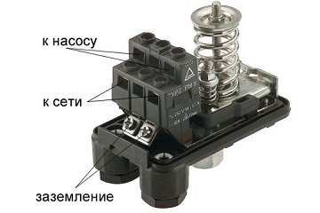
A sufficient level of control is provided by the pressure switch. It is a block with a plastic casing. Inside the housing there are two springs, each of which is “responsible” for setting the value of the extreme position (parameters for turning the pump on and off).
The relay is functionally connected to a hydraulic accumulator, which contains water and compressed air; the media come into contact through a flexible elastic membrane. In the working position, the water in the tank presses on the air through the dividing partition, creating a certain pressure. As water is consumed, its volume decreases and the pressure decreases. When a certain value (set on the relay) is reached, the pump turns on and water is pumped into the tank until the value set on the second spring is reached.
The connection diagram for a water pressure switch for a pump provides for connecting the equipment to a water supply system, a pump and an electrical power supply network.
For correct operation of the equipment, the pressure switch must be connected to the pump in such a way as to avoid the influence of turbulence and sudden pressure changes when the pumping equipment is turned on and during its operation. The best place for this is in close proximity to the hydraulic accumulator.
Before installing the pressure switch, pay attention to the operating mode recommended by the manufacturer, in particular, the permissible temperature and humidity values. Some models can only work in heated rooms.
IN classic scheme connecting the pressure switch to deep well pump autonomous water supply, the following equipment is installed in front of the relay:
When using many modern models For surface-type pumping units, installation of a water pressure switch for a pump can be much simpler: block installation is carried out when the relay is installed together with the pump. The pumping unit has a special fitting, so the user does not need to independently search for the most suitable appropriate place installation Check valve and filters for water purification in such models are often built-in.
Connecting a pressure switch to a submersible pump can also be done by placing the hydraulic accumulator in and even in the well itself, since waterproof design of the control equipment is often required and the operating conditions of the pressure switch may allow its location in such places.
 The connection diagram for the pressure switch and pumping station with a surface pump differs slightly from the diagram with submersible unit sequence of arrangement of some elements
 Obviously, the choice of installation method and location depends on the design of the equipment; usually all recommendations in this regard are indicated by the manufacturer in the accompanying documentation.
There are two commonly used schemes for connecting the pump automation and pressure switch. The method recommended by the manufacturer is always indicated in the accompanying documentation, but it will be useful to familiarize yourself with the possible schemes.
Important: When working, you must follow the sequence: first, the relay is connected to the water supply, and then to the electrical network.
The relay is mounted on the pipeline (the choice of location is made taking into account the above rules and recommendations). Installation is carried out using a tee connected to a transition fitting (it can be replaced by a drain hose).
Hydraulic accumulator equipped with a fitting having five outlets, to which they connect:
The relay, in turn, is connected to a submersible or external pump and a 220 V power supply.

The following recommendations apply to both options:
All the nuances are determined by the connection diagram for a submersible pump with a pressure switch or a similar connection for an external pumping unit supplied with the equipment.
To configure the pressure switch, you must install it in the system operating pressure. To do this, after assembling the circuit, the equipment should be turned on and wait automatic shutdown when the relay is activated. After this, the roof is removed and the settings are performed in the following sequence:


