It's no secret that currently the cost of repair and installation services door lock significantly exceeds the cost of a new locking device, so calling a specialist every time is quite expensive. In addition, not in all cases, the breakdown of the lock is so serious that it requires outside intervention. As practice shows, in about half of the cases it is quite possible to do it on your own, you just need to have some skill, a simple tool and a desire to “tinker” with the lock for some time. Do-it-yourself door lock repair, in fact, comes down to three main steps:
Oddly enough, the preparation for the repair of the castle is largely reduced to the psychological mood. After all, this kind of malfunction of locking devices often occurs unexpectedly and at the same time delivers a lot of trouble in the form of being late for work, disrupting important events, trips and other things. First of all, you should calm down and remember in time that unrestrained screams and curses against the castle will not contribute to its quick repair. Take a deep breath and start getting ready to repair the locking device.
 First of all, it is necessary to determine what type of locks the locking device of interest to us belongs to and what parts it consists of. There are a lot of castles, so we recommend that you read and look at photos on the Internet in order to identify your type by outward signs. In other words, according to those elements that are visible without opening the lock case.
Then you need to look (also in the photo) of what parts your type of lock consists of, so that later you can disassemble the case consciously, and not on a whim. Next, carefully inspect the fasteners of the lock in order to choose the right keys, screwdrivers and other tools to open its case.
In addition, you will need:
Having prepared mentally and having picked up a tool, you can start troubleshooting. Do not rush to disassemble the lock body, first inspect it carefully from the outside, insert the key and try turning it, listening for clicks. Usually at this stage it is possible to eliminate many types of breakdowns at once. If it became clear that the cause of the malfunction lies in the secret mechanism of the locking device, then it is necessary to open the case.
In fact, there are quite a few reasons for a lock malfunction, some are immediately visible, and some are difficult to determine. Oddly enough, the simplest breakdowns that can be fixed in five minutes can be difficult to detect for a non-professional. Therefore, we will describe the typical causes of a lock malfunction, which you need to pay attention to first. 
We note right away that repairing the mechanism of a plate (lever) lock is far from always possible without the involvement of a professional. And in some cases, it is impossible to repair such a lock at all, since components for it are not produced. If one of the levers is damaged and there is a replacement for it, then the damaged plate must be carefully removed. For this operation, special skill is not required, which cannot be said about the stage of installing a new plate. This is where you will need all the patience. 
When examining the lever lock mechanism, it is necessary to pay attention not only to the plates, but also to the condition of the springs. Quite often, the spring that popped out becomes the cause of the breakdown of the mechanism. Usually such a breakdown is noticeable immediately, but as they say, cases are different, be careful. Often, having opened the case and removed the lock, you do not notice any problems, moreover, the key enters the keyhole freely and turns well in it, the mechanism starts to work like a clock. When the lock is installed in its original place, the problem returns - the secret mechanism refuses to work, there can be two reasons:
A lock with a cylindrical secret is repaired only by replacing the cylinder. Fixing a secret in this case impossible, but it is also true that spare parts for such locks are much easier to obtain than for lamellar locking devices. Replacing the cylindrical secret is carried out in the following order. 
Summing up, we note that the repair of the castle front door, like any other, it requires desire, patience and some skill, although a good owner or even a hostess can fix most breakdowns with their own hands. When making any manipulations with a damaged lock, do not forget to familiarize yourself with the features of its design, otherwise you can not only not solve the problem, but also aggravate it. Good luck to you repair work!
(Laboratory work)
EXPERT RESEARCH OF LOCKS
§ 1. Device, principle of operation and classification of locks
To lock various rooms, safes, cabinets, drawers and other objects, various mechanisms and devices are used. One of the most common means of locking are padlocks.
Lock- this is a product used to lock doors and has a complex combination of locking devices or working pins that provide blocking 1.
Mechanical locks, regardless of their purpose and design, have the following main parts: body, deadbolt, locking device. Many locks have safety devices or elements of lock parts that perform safety functions. Each lock comes with one or more standard keys.
The case is a part of the lock, which serves to place the details of its mechanism inside it. The case of a mortise lock consists of a base to which the front plate and cover are attached. Stands are located on the base of the case. for various purposes. On the upper side of the padlock with a lid, there are two holes for the ends of the shackle, and the keyhole is made in the lid. Many padlocks have a monolithic body. The shape and size of lock cases can be varied, and their facial surfaces often finished with galvanic, paintwork, enamel and other protective and decorative coatings. Paddle control locks are distinguished by the presence of two covers: the main and additional
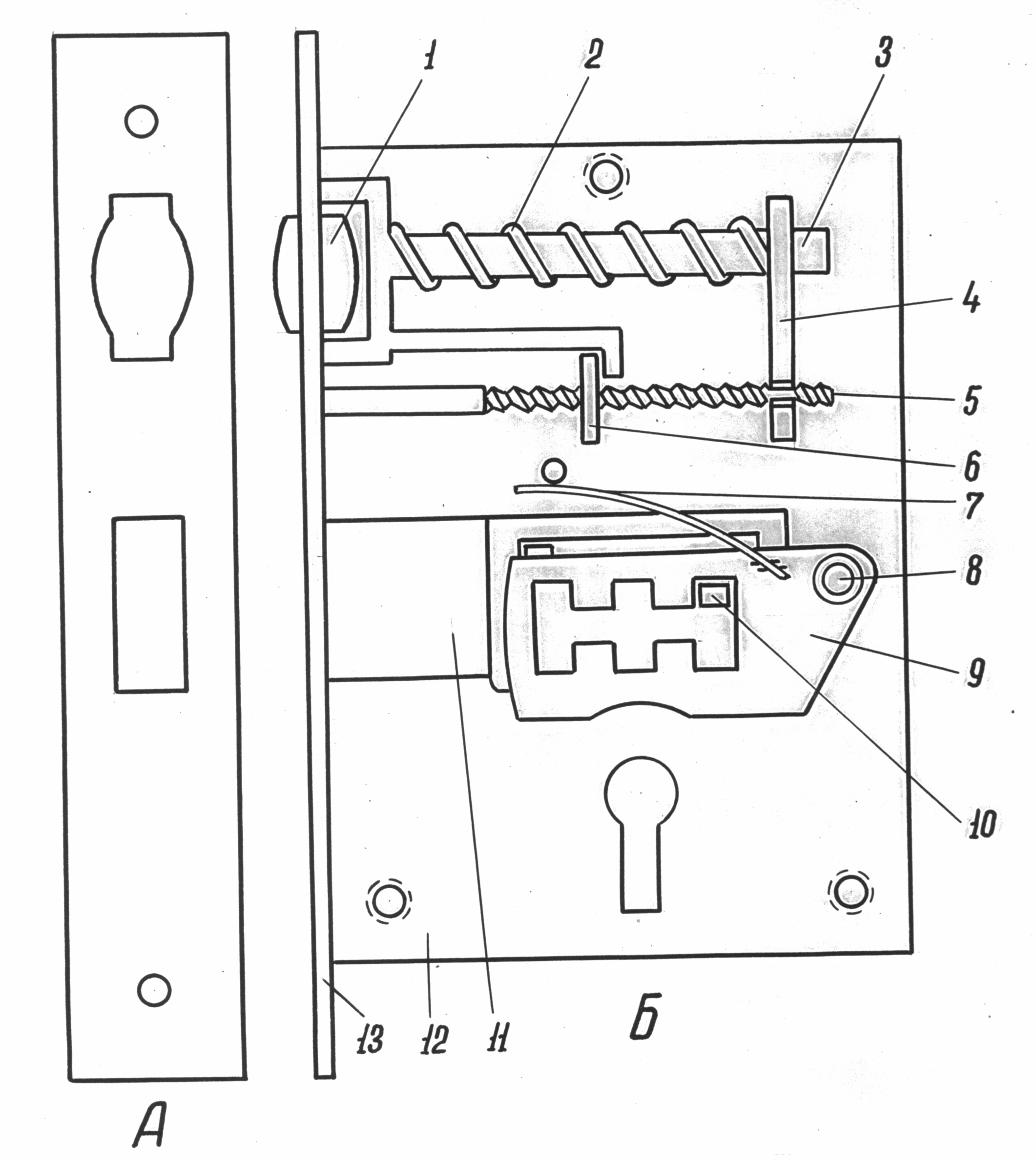
Body (control), between which is placed a control insert (Fig. 1). 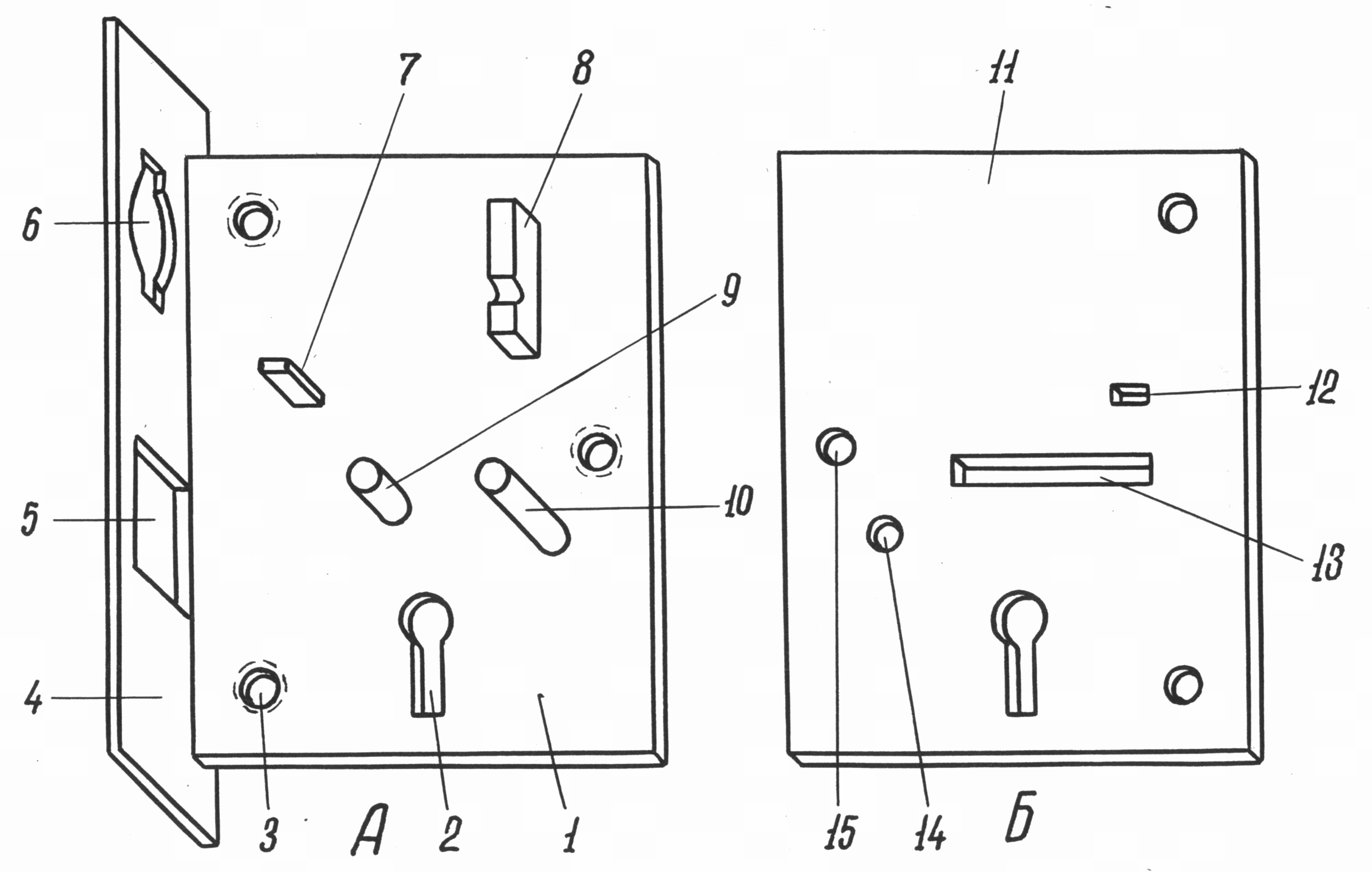
Rice. 1. Elements of the mortise lock body:
1 - the base of the lock body; 2 - well for a key; 3 - hole
With thread for attaching the housing cover; 4 - the front plate of the lock;
5 - a hole in the front plate for lever springs; 6 - hole
In the front plate for the retainer roller; 7 - thrust rack for lever springs; 8 - a persistent level of a clamp; 9 - guide rack;
10 - axis levers; 11 - case cover; 12 - cutout for a thrust stand
Lever springs; 13 - cutout for the deadbolt stand; 14 - axle hole
Suwald; 15 - hole for attaching the cover to the base of the case
A deadbolt is a part that serves to lock the lock by moving its head into the cutout of the striker plate or the lockable end of the shackle. The design of the deadbolt may be different, but in any case it has two mandatory element- shank and head (Fig. 2). On the bolt shank there are various cutouts and posts with a certain functional load (Fig. 3). The lock can have either one or several deadbolts or a deadbolt with several heads.
The locking device is designed to fix the deadbolt in the locked or unlocked position of the lock. Various kinds of springs act as fixing parts, threaded connections deadbolt with body, protrusions on the moving parts of the locking mechanism and levers. Of all the fixing parts, levers are structurally the most diverse.
Rice. 2. Lock bolts with various locking mechanisms.
Bolt heads highlighted in black
Rice. 3. The bolt of a lever lock, locked with two turns of the key:
1 - head; 2 - shank; 3 - cutout for the guide rack; 4 - rack;
5
- cutout for the lever axis; 6
- cutout for key beard
The suvalda is a metal plate with a window in the central part (Fig. 4). The window has recesses for the deadbolt stand, located above and below or only above, which act as locking elements. Sometimes for the same purpose, recesses located at the bottom of the levers are used instead of windows. The shape, design features of levers and their elements are quite diverse (Fig. 5). Each lever has a spring and is movably fixed on the axle or guide posts. In separate locks, one spring is used, common to all levers. The number of levers, their location, thickness, dimensions of the recesses of the windows together are the secrecy mechanism of the lever lock. 
Rice. 4. Suvalda for a lock that can be locked with two turns of a key:
1 - level window; 2 - upper recesses of the lever window;
3 - lever spring; 4 - a hole for the axle; 5 - cutout for key beard;
6 - lower recesses of the lever window
Rice. 5. Various constructive types of levers
The secrecy mechanism is a device in mechanical locks, which, when interacting with a regular code carrier (for example, a key), communicates it with the deadbolt or creates conditions for its movement from some other body (handle, steering wheel, etc.). Parts specially designed to make it difficult to access the details of the locking mechanism and thereby complicate the possibility of unlocking the lock with foreign objects are also included in the system of the secrecy mechanism. These parts are called fuses. Fuses are made in the form of plates of a certain shape and size or metal rods and are mounted in a longitudinal or transverse position relative to the base of the housing (Fig. 6). The functions of a kind of safety device are also performed by the configuration of the well for the key. 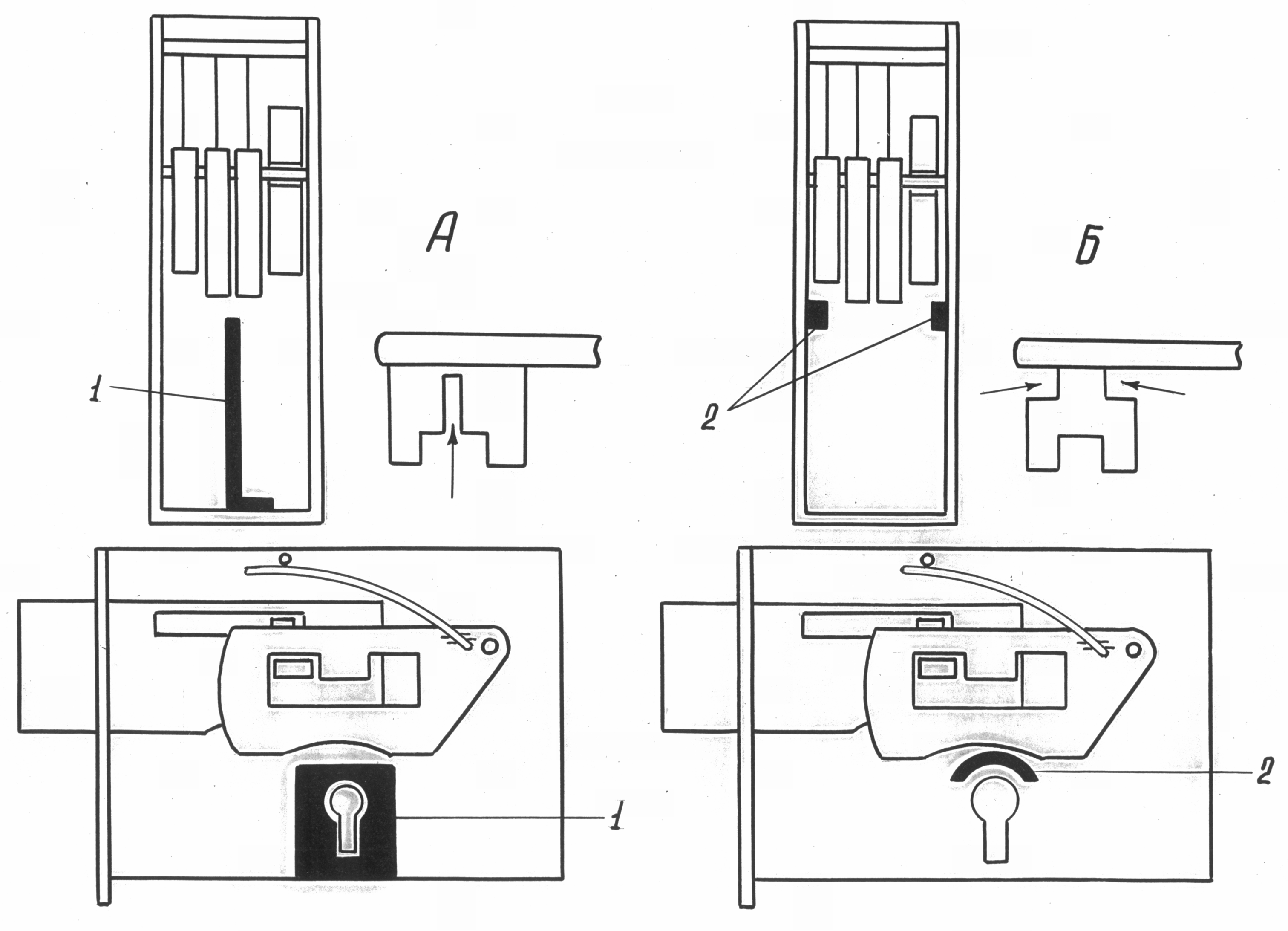
Rice. 6. Fuses in lever locks:
A- longitudinal fuse; B- cross fuse.
1 - longitudinal fuse plate; 2 - protrusions of the transverse fuse. The arrows show the cuts on the barbs of the keys.
to locks with fuses
Key- this is a product that serves to actuate the locking devices of the lock or the pins of the cylinder mechanism and provides the necessary exit of the deadbolt 1. Depending on the system of the locking mechanism, the keys are manufactured in various design options.
The keys of non-lever locks, consisting of a head, a rod, one or two barbs, are the simplest in their design. The key for a lock with a rack mechanism is a cylindrical or rectangular rod, on which cuts are located at certain distances and at a certain angle. The keys to lever locks have one or two beards with a different number of protrusions and cutouts (Fig. 7). 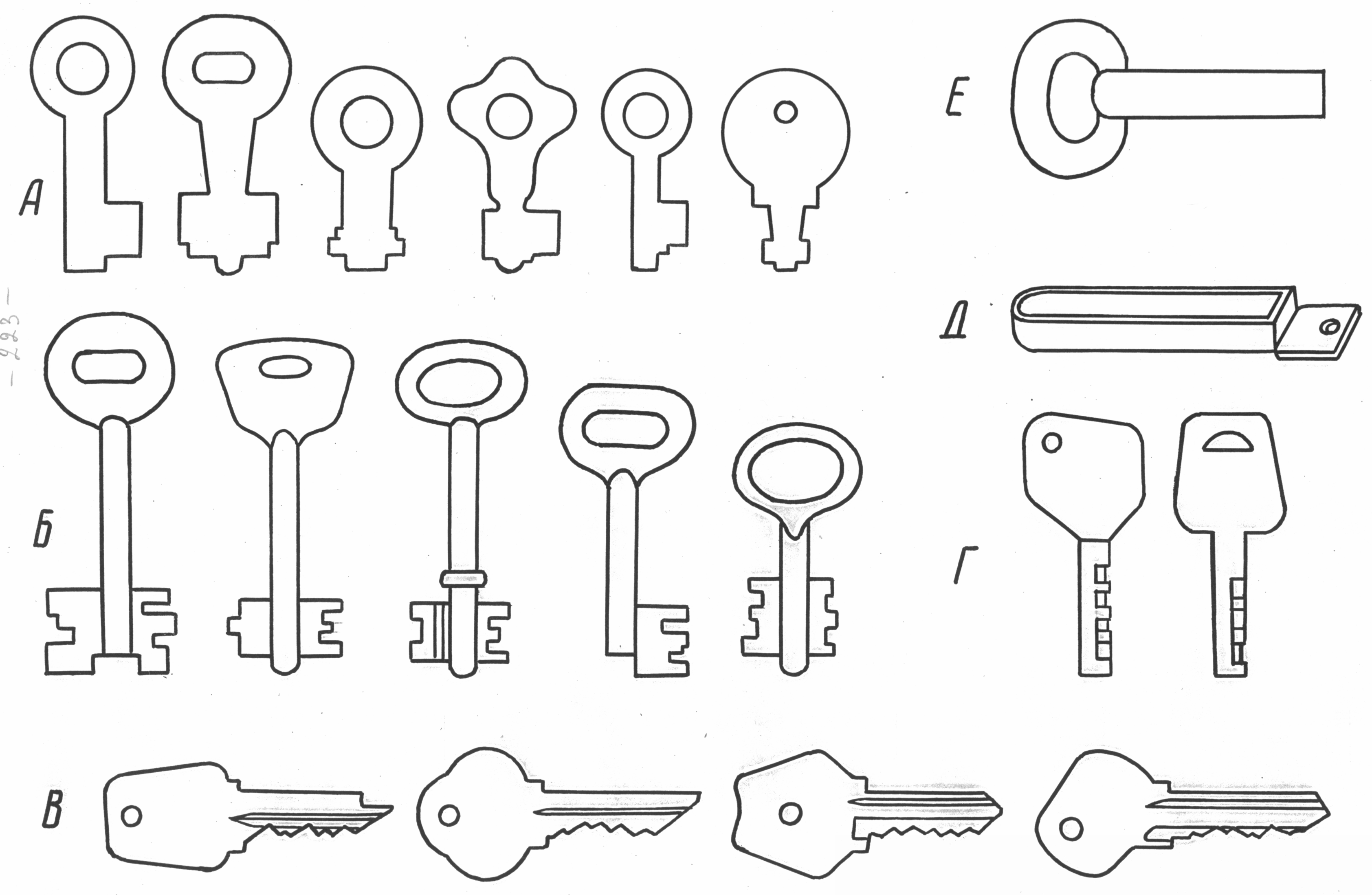
Rice. 7. Keys to locks different system locking:
A- keys to leverless locks; B- keys to lever locks;
IN- keys to cylinder locks; G- keys to cylinder locks
"Abloy"; D- the key to the magnetic lock "Surprise"; E- key to screw lock
The design of keys for cylinder locks depends on the number of rows of pins in the locking mechanism. The key to a single-row cylinder mechanism is flat, with protrusions and cutouts separating them on one of the end faces of the plate. The key to the lock with two rows of pins located opposite each other has protrusions and cutouts on two opposite ends. The key to the cylinder plate lock looks similar.
If the lock is equipped with three or more rows of pins, then the key has a cylindrical rod ending in three or more plates with protrusions and cutouts on the end of each of them (Fig. 8). 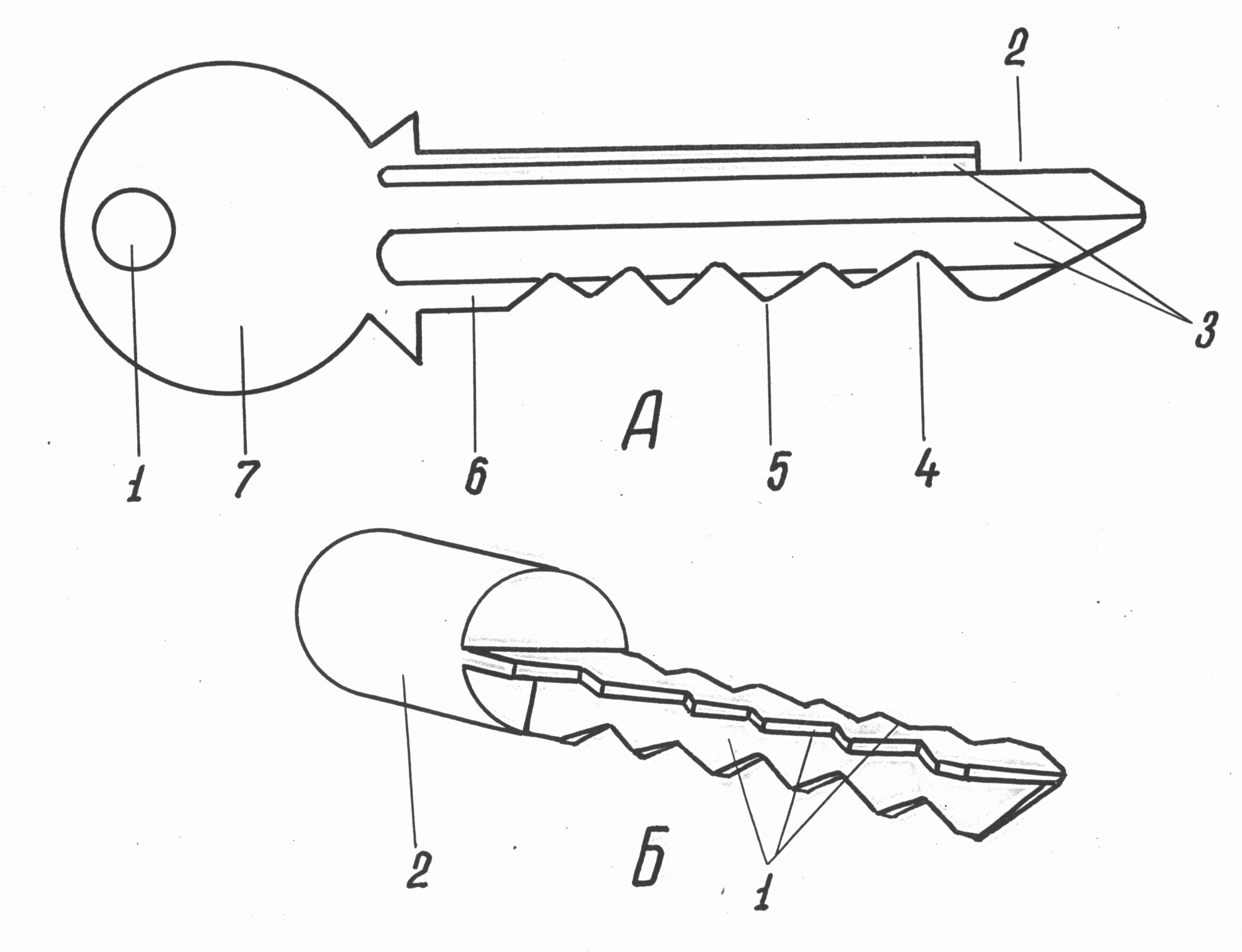
Rice. 8. Keys for locks with cylinder mechanisms:
A- the key to the lock with one row of pins: 1 - ear; 2 - propyl for
fuse; 3 - grooves on the rod; 4 - notch on the rod; 5 - ledge
on the rod; 6
- rod; 7
- key head. B- part of a key for a lock with three rows of pins: 1
- rows of cutouts and protrusions; 2
- part of the key stem
On a semicircular cross section, the core of the key to the lock of the “Abloy” type has cutouts of different width and angle of inclination to the diametrical plane of the core (Fig. 9). 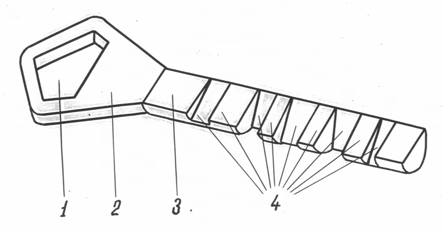
Rice. 9. Key for Abloy lock:
1
- ear; 2
- head; 3
- rod; 4
- ledges
The keys to screw locks have a rod of a certain profile and size, at one end of which there is a head (sometimes the L-shaped bent end of the rod performs the functions of the head), and at the other - a tubular element with a certain internal transverse profile (Fig. 10). Sometimes, instead of a tubular element, the key shaft in this place is given a cruciform or polyhedral shape. 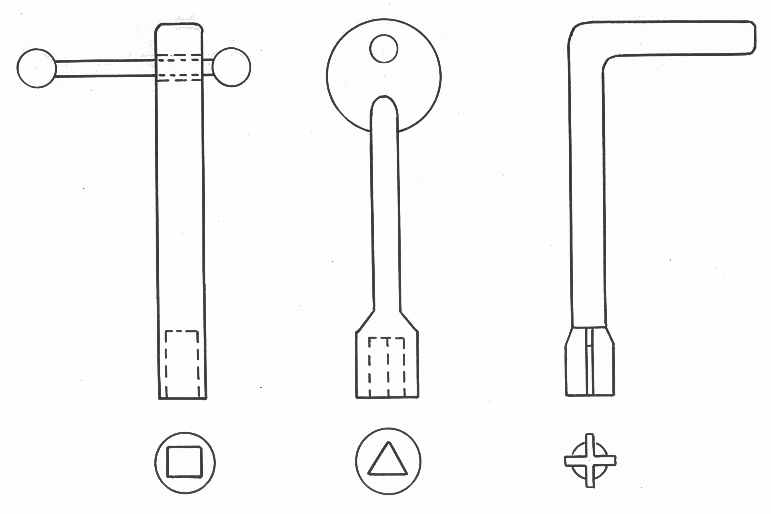
Rice. 10. Keys for screw locks
For mechanical locks with a coded (cipher) locking system, the key is a certain combination of letters or numbers. Such locks are unlocked and locked by setting manually (without a key as a separate material object) the disks of the locking mechanism to a certain position.
In addition to the mechanical action of the key elements on the parts of the locking mechanism in a number of locks, the movement of the mechanism parts can be carried out by means of magnetic or electromagnetic fields. There are locks, the key to which is a certain image, for example, the papillary pattern of the finger of a particular person, which is transformed into a key using a computer. Sometimes there are several keys assigned to one lock. various features rod or barb elements in contact with the parts of the locking mechanism. So, several keys (up to 14), alternately in a certain sequence entered into the lock to unlock it, have home-made and handicraft locks that are widespread in Mongolia and found on the territory of Buryatia and Tuva original design. They lock automatically.
The principle of operation of locks is determined by the design features of the locking mechanisms. Leverless locks are the simplest in design and principle of operation. A leverless padlock (Fig. 11) consists of a body and a shackle, one end of which is fixed on the axis, and on the other (lockable) there is a cutout in the form of a recess or a through window for the head, loaded with a spring. The lock cover has a hole for a key.
Rice. eleven. The principle of operation of a padlock without a lever lock:
A B 1 - frame; 2 - deadbolt; 3 - bolt head; 4 - cutout at the lockable end of the shackle;
5 - lockable shackle end; 6 - bow; 7 - shackle axis; 8 - bolt spring;
9 - key hole
The lock is unlocked in the following order: when the key is inserted into the keyhole and turned clockwise, its beard presses on the bolt shank and, overcoming the elasticity of the spring, moves the bolt to the right. In this case, the head of the bolt comes out of the cutout in the lockable end of the shackle. By rotating the shackle on the axis, its lockable end is removed from the lock body. In a number of such locks, the shackle independently exits by means of a special spring. In some types of leverless padlocks, the shackle does not rotate on the axis, but, spring-loaded from below, is pushed out of the body.
Most of these locks are locked without a key. To do this, it is necessary to press on the shackle from top to bottom, its lockable end will enter the body and begin to put pressure on the head of the deadbolt, pushing it to the side. As soon as the notch on the shackle is against the bolt head, it will return to its original position under the action of the spring and will be locked.
Leverless locks with two bolts, independently fixed on separate axles and loaded with a common or separate springs, are unlocked by turning a double-bit key by 90º. At the same time, the key beards push the bolt shanks to the sides, and the bolt heads come out of the recesses in the lockable ends of the shackle (Fig. 12).
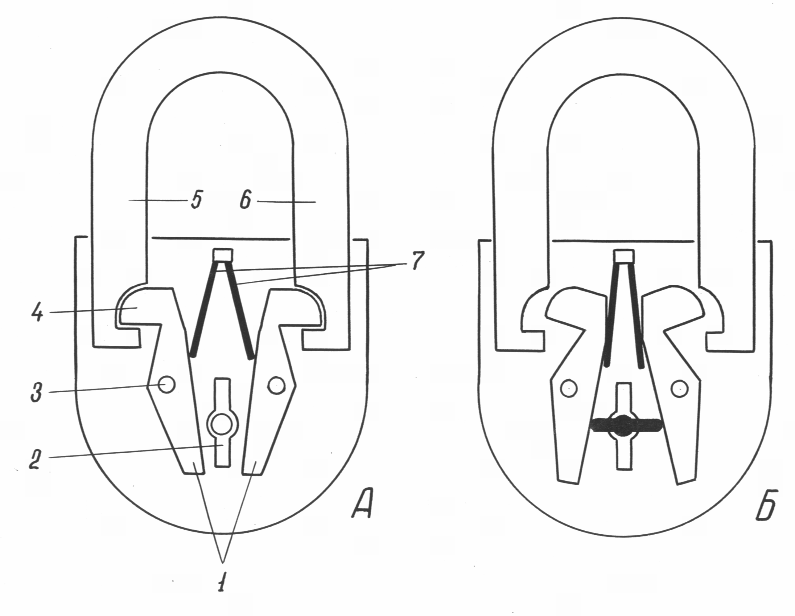
Rice. 12. The principle of operation of a padlock without a lever lock with two bolts:
A- the lock is in the locked position; B- the lock is in the unlocked position.
1 - bolts; 2 - well for a key; 3 - bolt axis; 4 - bolt head;
5, 6 - lockable shackle ends; 7 - bolt springs
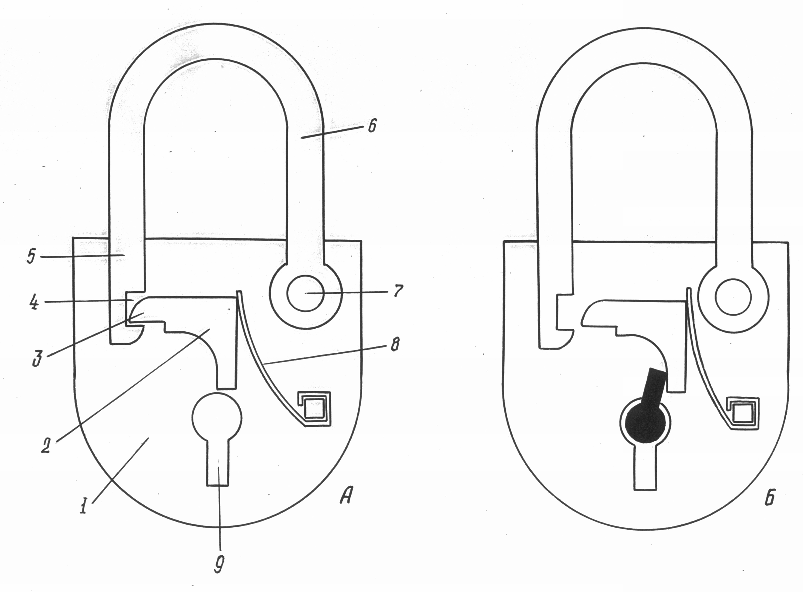
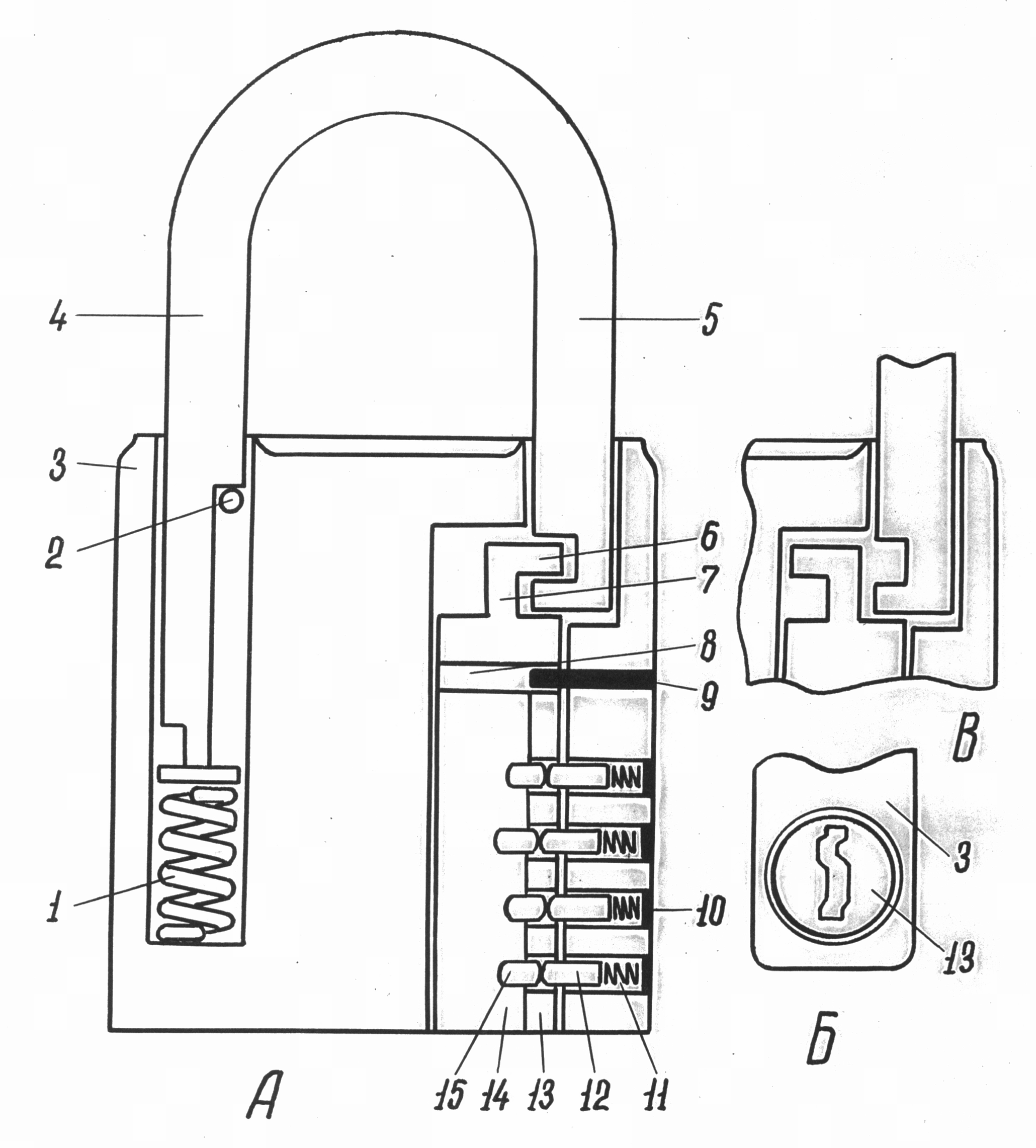
Leverless control locks are widely used (Fig. 13). A feature of their design is the presence of an additional cover. Between it and the main cover of the case, a control insert is placed (a piece of paper of a certain size with the signature of the responsible person or a seal imprint), which closes the keyhole and is visible through the window in the additional cover. The additional cover in the locked position of the lock is fixed by the free end of the shackle passing through the hole in its upper face. 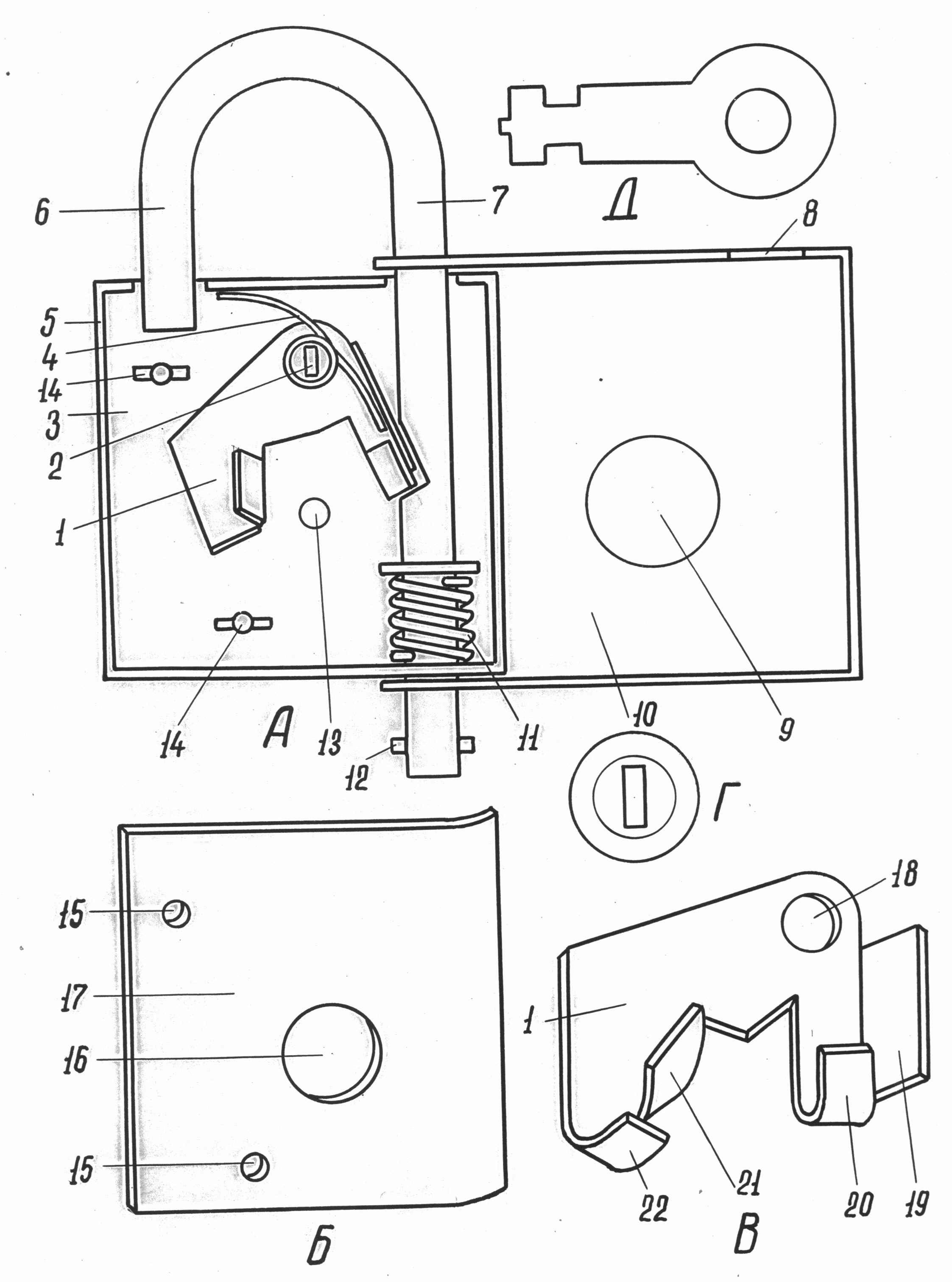
Rice. 13. The device of a hanging non-lever control lock:
A- lock; B- case cover; IN- deadbolt; G- key; D- key.
1 - bolt shank; 2 - bolt axis and springs; 3 - the base of the body;
4 - bolt spring; 5 - side wall; 6 - the free end of the bow;
7 - lockable shackle end; 8 - a hole for the free end of the bow;
9 - control window; 10 - additional (control) cover; 11 - shackle spring; 12 - limiter; 13 - key stand; 14 - a rack for fastening of a cover of the case; 15 - holes for fixing the housing cover; 16 - a hole for a key; 17 - case cover; 18 - a hole for the axle; 19 - thrust ledge for the spring; 20 - bolt head; 21 - protrusion for the key;
22 - a stand that reinforces the protrusion for the key
A lock with a slatted deadbolt is arranged in a peculiar way (Fig. 14). In such a lock, on the lower face of the bolt shank, there are cutouts of various sizes located at a certain angle and at different distances from each other. On the core of the key there are inclined cuts, dimensional and angular characteristics which correspond to the gaps between the notches on the bolt shank. When the key is pressed into the keyhole, the cuts on it alternately engage with the inclined protrusions between the cutouts on the bolt, which creates a force for its movement and compression of the spring. During the extraction of the key from the well, the bolt is returned by the spring to its original position, corresponding to the locked state of the lock. To fix the deadbolt in the unlocked position, a locking screw is used, which with its head extends beyond the surface of the lock body attached with inside doors. ![]()
Rice. 14. Rim lock device:
A- lock; B- deadbolt; IN- key; 1 - well for a key; 2 - bolt spring; 3 - a hole in the body for fixing the lock; 4 - guide rod
Bolt springs; 5 - recess in the bolt shank; 6 - slot in the body;
7 - bolt fixing screw; 8 - bolt head; 9 - front plate;
10 - a hole for fastening the lock; 11 - bolt shank;
12 - propyl in the shank of the bolt
Significant amount constructive types rack locks have two or more heads on one bolt that simultaneously extend beyond the front plate when locking the lock.
The simplicity of the device of leverless and rack locks allows criminals to relatively easily remove them as obstacles, using the simplest master keys, and sometimes simply foreign objects (a nail, an awl, a piece of wire, etc.).
A distinctive feature of lever locks is the presence of a lever (lever) in their locking mechanism as an element of fixing the deadbolt in a certain position.
Structurally, lever locks are made in various options, with more or less nodes and parts. Some types of such locks are shown in Fig. 15 and 16. 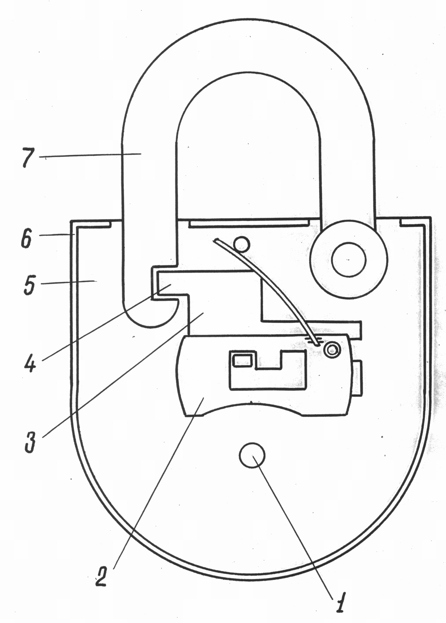
The interaction of the details of the locking mechanism of the lever lock occurs as follows (Fig. 17). In the locked position of the lock, the bar of the bolt shank is fixed in the upper notch of the lever window closest to the bolt head. When the key is turned, the cutout of the barb raises the lever to such a height that the bar of the bolt shank is opposite the free space between the protrusions separating the notches of the lever window. Turning further, the key with another ledge of the beard moves the bolt inside the case. Then the key beard goes down, and the lever is lowered under the action of the spring, while the stand of the bolt shank is fixed by the second notch of the lever window. The interaction of parts during the locking of the lock occurs in a similar way and is carried out by turning the key in the opposite direction.
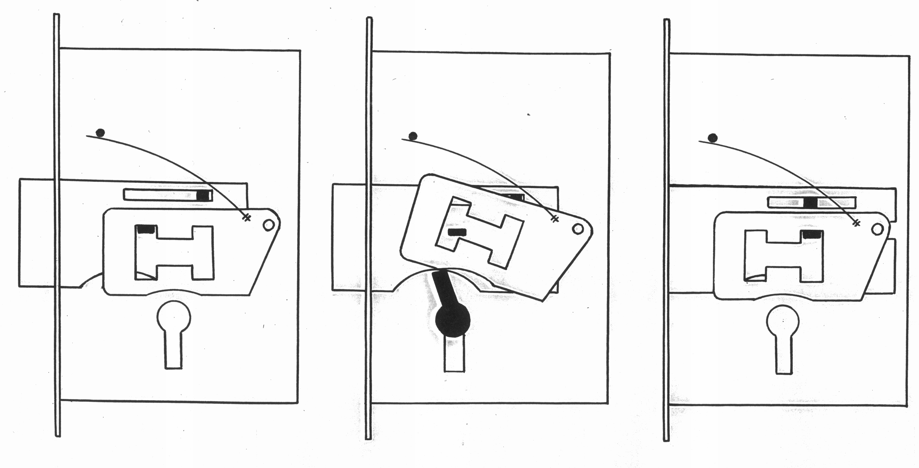
Rice. 17. The principle of operation of the lever mechanism
If there are several levers in the lock, each of them, in the process of unlocking and locking the lock, is raised by the corresponding cutout of the key beard to a strictly defined height, ensuring free passage of the deadbolt shank stand in the lever window.
The original design of the locking mechanism has such a kind of lever lock as a magnetic padlock "Surprise".
In it, the functions of levers are performed by freely suspended pins, which, when the lock is unlocked, are oriented by the magnetic fields of the key in a certain position and allow the bolt shank to move in the lock body (Fig. 18). 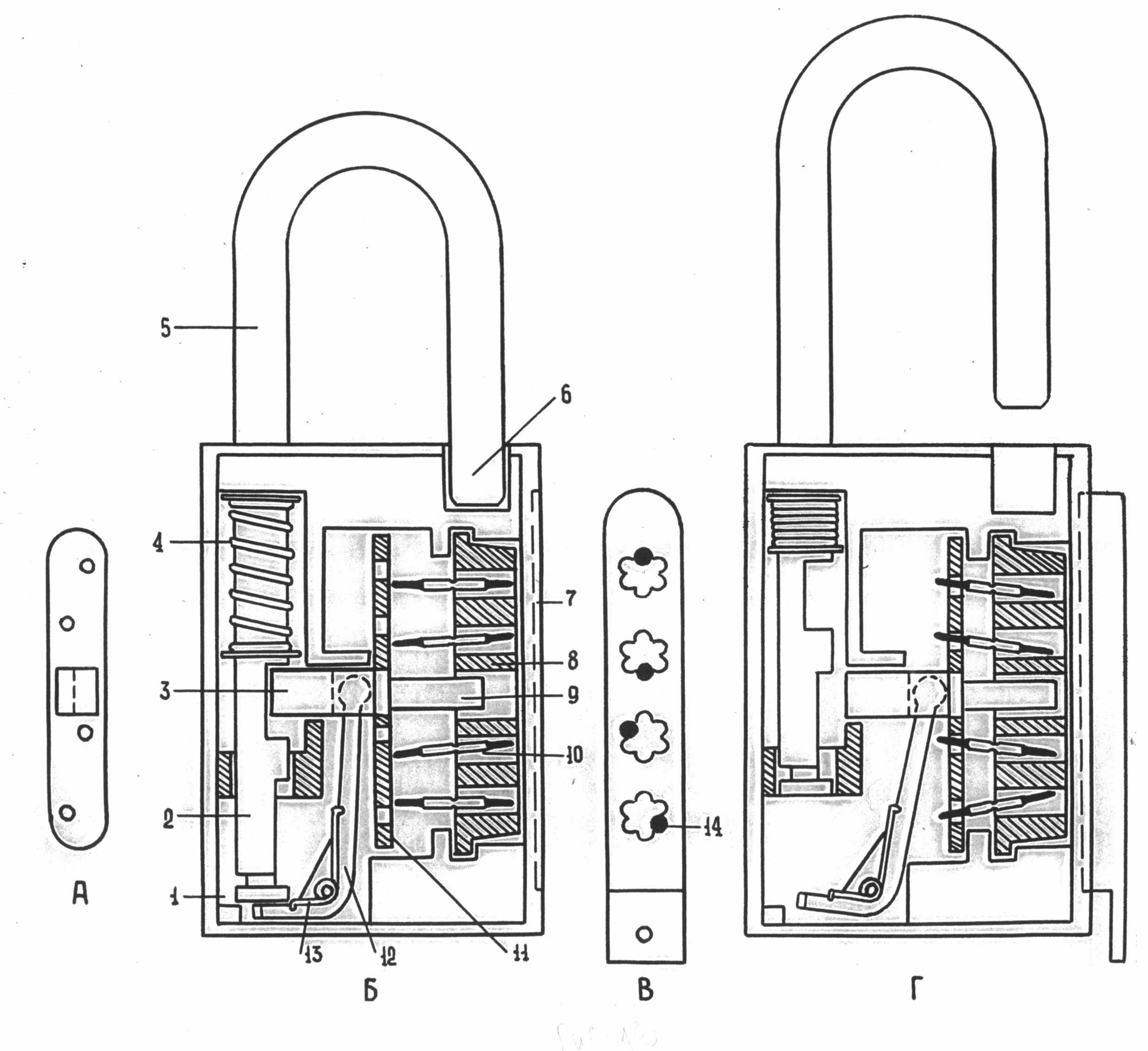
Rice. 18. The device of the hanging magnetic lock "Surprise":
A- the location of the holes on the bolt shank; B- lock in locked
position; IN- key; G- the lock is in the unlocked position; 1 - frame;
2 - lockable shackle end; 3 - bolt head; 4 - shackle spring;
5 - bow; 6 - the free end of the bow; 7 - deepening for a key; 8 - block of pins; 9 - bolt guide rod; 10 - pin; 11 - bolt shank; 12 - two-arm lever; 13 - lever spring; 14 - key magnet
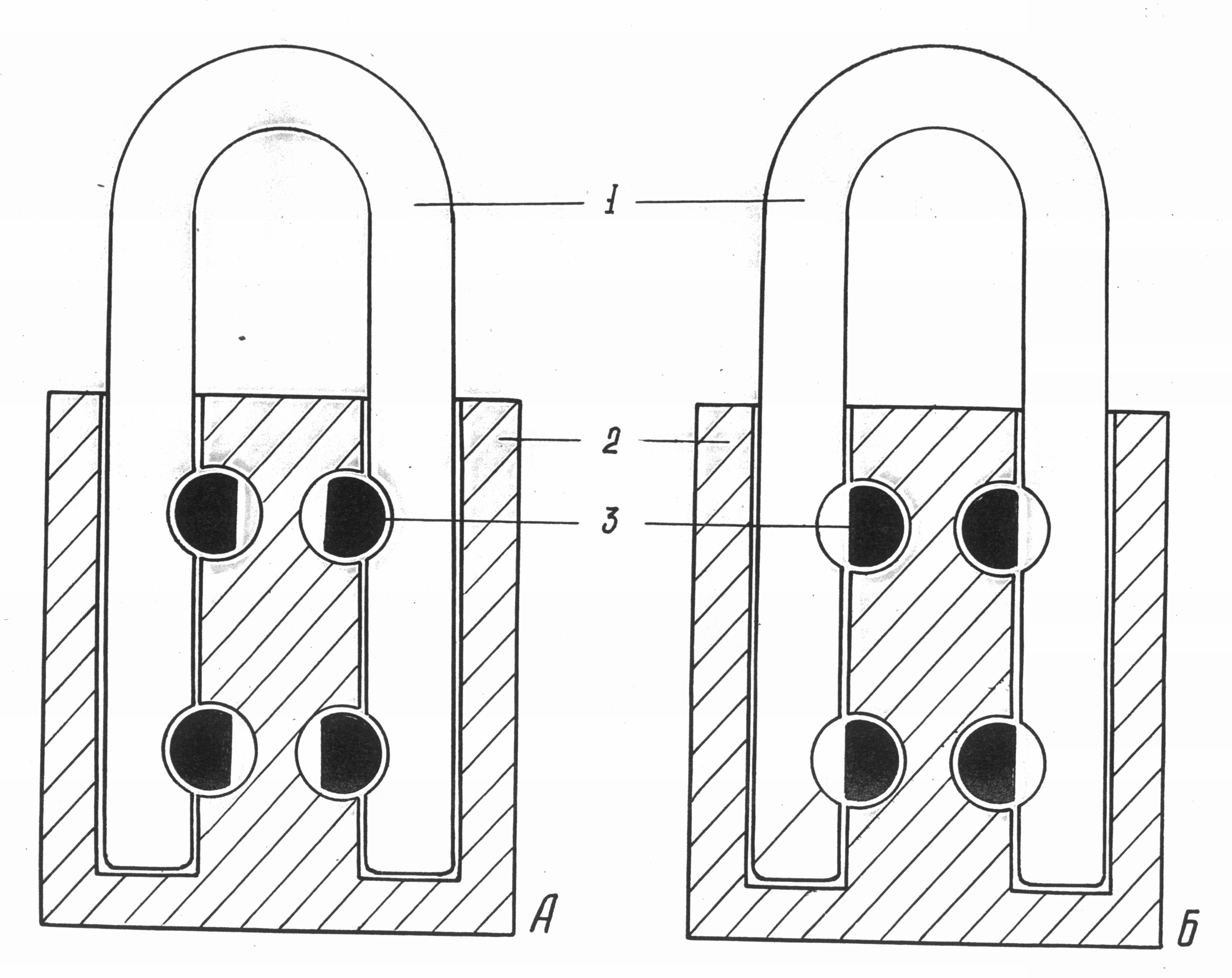
Locks with a cylinder mechanism are very diverse and the most complex in their design. Their mechanism consists of a cylinder located inside the case (Fig. 19). In the cylinder, along its longitudinal axis, there is a borehole with curly side faces - a groove for the key. The pin sockets are arranged in one row and connect the keyhole to the surface of the cylinder. The cylinder body has similarly positioned body pin sockets. Outside, these nests are closed with plugs or one common plate. In cast padlocks, the function of the cylinder mechanism body is performed by a hole in the lock body. Pins of various lengths are placed in the cylinder seat, and the same lengths are placed in the housing sockets. The housing pins are supported by helical springs.
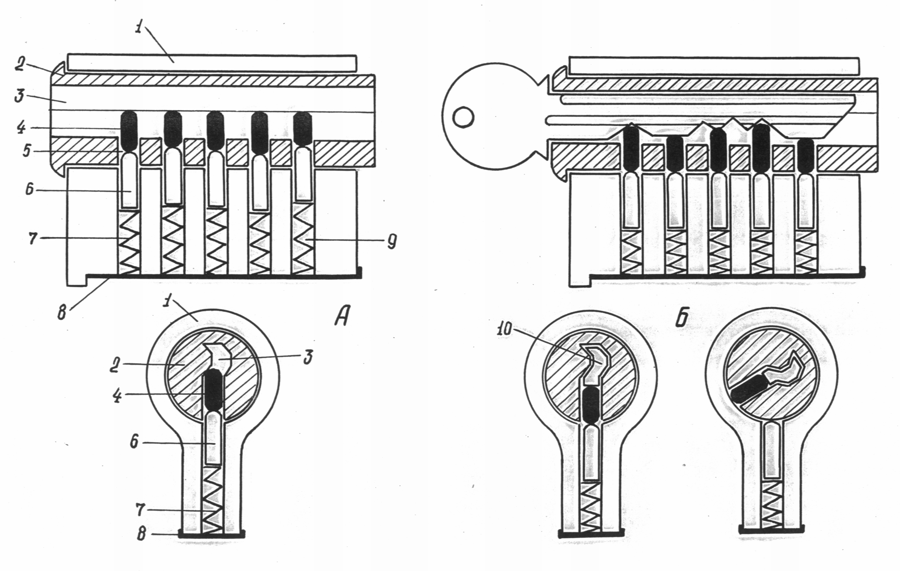
Rice. 19. The device of the cylinder mechanism:
A- the mechanism is in the locked position; B- the mechanism is in the unlocked position;
1 - frame; 2 - cylinder; 3 - well for a key; 4 - cylinder pin;
5 - cylinder seat; 6 - housing pin; 7 - housing spring;
8 - case cover; 9 - housing socket; 10 - key
In the locked position of the mechanism, the cylinder seats and the housing coincide. Under the action of the springs, the pins of the housing are partially pushed into the sockets of the cylinder and block the boundary between the housing and the cylinder, thereby fixing the latter and preventing its rotation.
When the key is inserted into the well, the cylinder pins are recessed into the sockets so that the plane of their contact with the body pins is aligned with the boundary between the body and the cylinder. In this position of the pins, the cylinder is freely rotated by the key and the leash moves the bolt.
Cylinder locks are made in hanging, mortise and laid on versions. Among padlocks with a cylinder mechanism, samples with a cast body are most widely used (Fig. 20).
Rice. 20. The device of a padlock cylinder with a cast body:
A- lock; B- view of the cylinder from below; IN- lock in unlocked position
(cylinder rotated); 1 - shackle spring; 2 - stop pin
Temples; 3 - frame; 4 - the free end of the bow; 5 - lockable end
Temples; 6 - bolt head; 7 - shank (neck) of the deadbolt; 8 - groove
For thrust pin; 9 - thrust pin of the cylinder; 10 - stub;
11 - housing spring; 12 - housing pin; 13 - cylinder;
14
- well for a key; 15
- cylinder pin
The design of cylinder locks is peculiar, in which the functions of pins are performed by plates placed in the cylinder (Fig. 21). They are located in the through transverse slots of the cylinder and are supported by ledges on helical springs. In the center of the plates, rectangular windows are cut out, the location of which along the vertical axis on each plate is individual. On inner surface the body of the locking mechanism has arcuate recesses arranged opposite each other for the lower and upper faces of the plates. 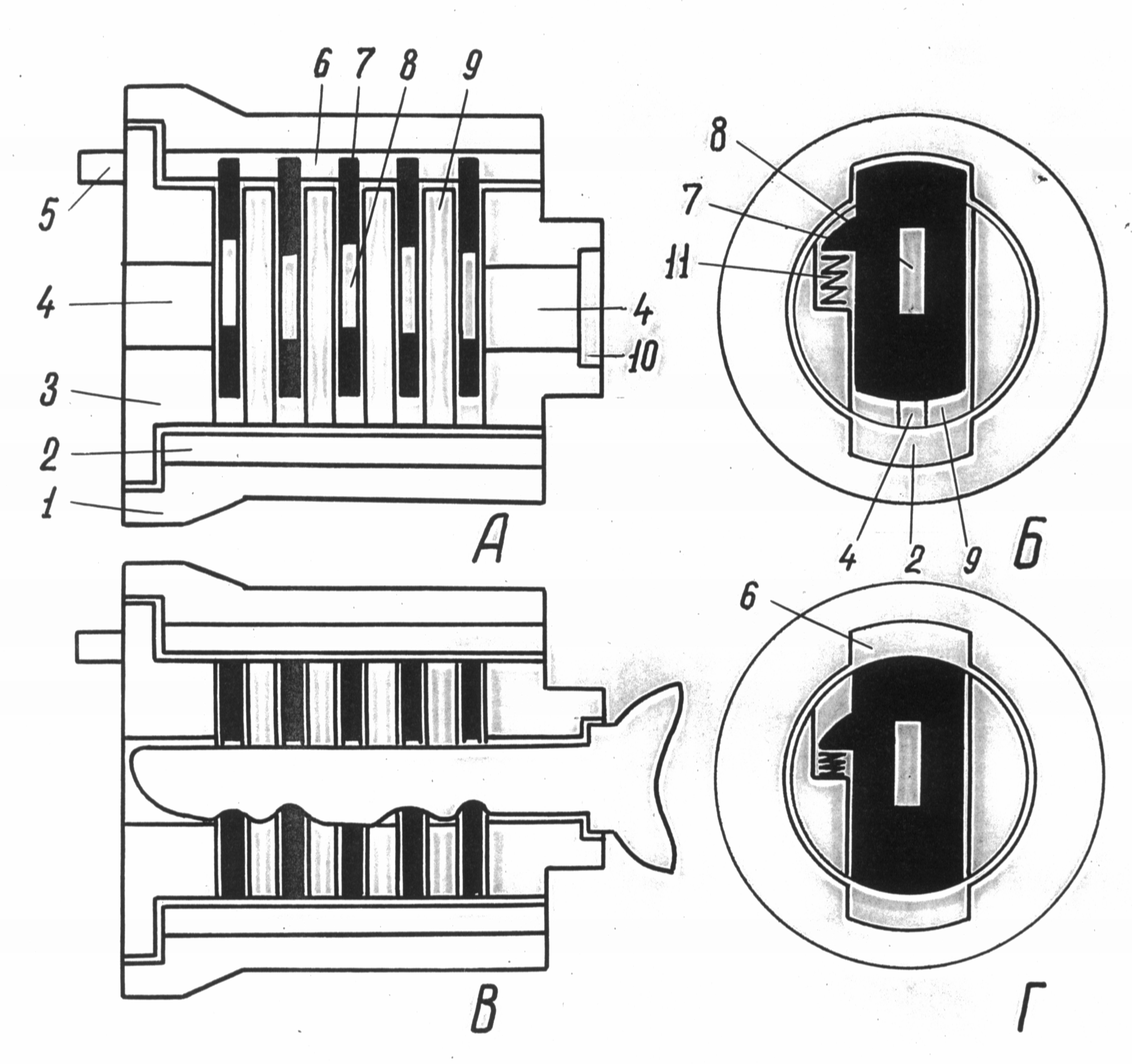
Rice. 21. The device of the cylinder mechanism with a transverse arrangement of plates in the cylinder: A, B
V, G- cylinder mechanism in the unlocked position; 1 - frame;
2 - the lower groove of the body; 3 - cylinder; 4 - well for a key; 5 - leash;
6 - the upper groove of the body; 7 - plate; 8 - a window in the plate; 9 - jumper; 10 - a shoulder for a stop of a key; 11 - spring
In the locked position of the mechanism, the plates, under the influence of springs, enter the recesses of the body, fixing the cylinder. When the key is inserted into the well, its protrusions (or cutouts) pass through all the windows of the plates and lower the plates by a certain amount, leading them out of the recesses of the body. Released from fixation, the cylinder rotates in the body and moves the deadbolt with a leash.
Abloy cylinder locks 1 are widely used. Regardless of the purpose and method of attachment to the object, these locks have the same type of locking mechanism, the secret of which lies in a cylinder made of disks (Fig. 22).
Rice. 22. The device of the cylinder mechanism of the lock "Abloy":
1 - the main disk (washer); 2 - wide cutout in the case; 3 - ledge
On the main drive; 4 - additional disk (washer); 5 - frame; 6 - leash; 7 - locking pin; 8 - deepening on the main disk; 9 - deepening
On an additional disk; 10 - narrow cutout in the case; 11 - plane
Cut when dismantling the castle; 12 - restrictive sleeve; 13 - key;
14 - body of the block of the cylinder mechanism of the lock
The disks (washers) of the cylinder are divided into main - movable and additional - fixed. The number of disks, depending on the model of the lock, may be different. The main discs are round metal plates with a ledge and notch around the circumference and a semicircular key hole in the center. Mutual arrangement protrusion, recess and diametrical plane of the key hole on each cylinder disc individually. Additional washers are made of thin bronze tape. Due to its springy properties, the main disks are fixed in the position in which they were after the key was removed from the well. These washers are the same and, alternating with the main washers, are fixedly fixed in the mechanism case with the help of arcuate protrusions that go into a wide cutout of the case. Notches are located on the additional washers against the fixing arcuate protrusions, in the center there are round holes for the key.
On the side surface of the beaker-shaped body opposite each other there are wide and narrow longitudinal cuts. A leash is attached to the outer side of the bottom of the case. A wide cutout is designed to fix additional washers and move the protrusions of the main disks in it when they are turned with a key. A locking pin made of steel or brass wire is placed in a narrow cutout. The locking pin can be made in two versions: as a straight rod or in the form of the letter "L". In the latter case, the short end of the rod is located in a recess on the side surface of the housing bottom against a narrow cutout and is supported from below by a spiral spring.
The body of the locking mechanism with a cylinder made of disks and a locking pin is placed in the socket of the lock body and fixed in it with a restrictive sleeve with a round key hole in the center. On the inner surface of the socket in the lock body there is a longitudinal recess for the locking pin.
In the locked position of the mechanism, the main disks are in such a position that the semicircular holes for the key in their central part coincide and form a longitudinal semicircular channel for the entire length of the cylinder (Fig. 23). At the same time, the recesses on the main disks are not located along one line, and the locking pin, being partially placed in the longitudinal recess of the socket of the lock body, fixes the body of the locking mechanism in it.
After inserting the key into the well and turning it by 90º, each ledge on the key stem turns the corresponding main disk to a certain angle. As a result, the recesses on all the main discs are aligned with the narrow cutout of the body and the recesses on the additional washers, forming a longitudinal recess and releasing the body of the locking mechanism from fixing in the seat of the lock body. 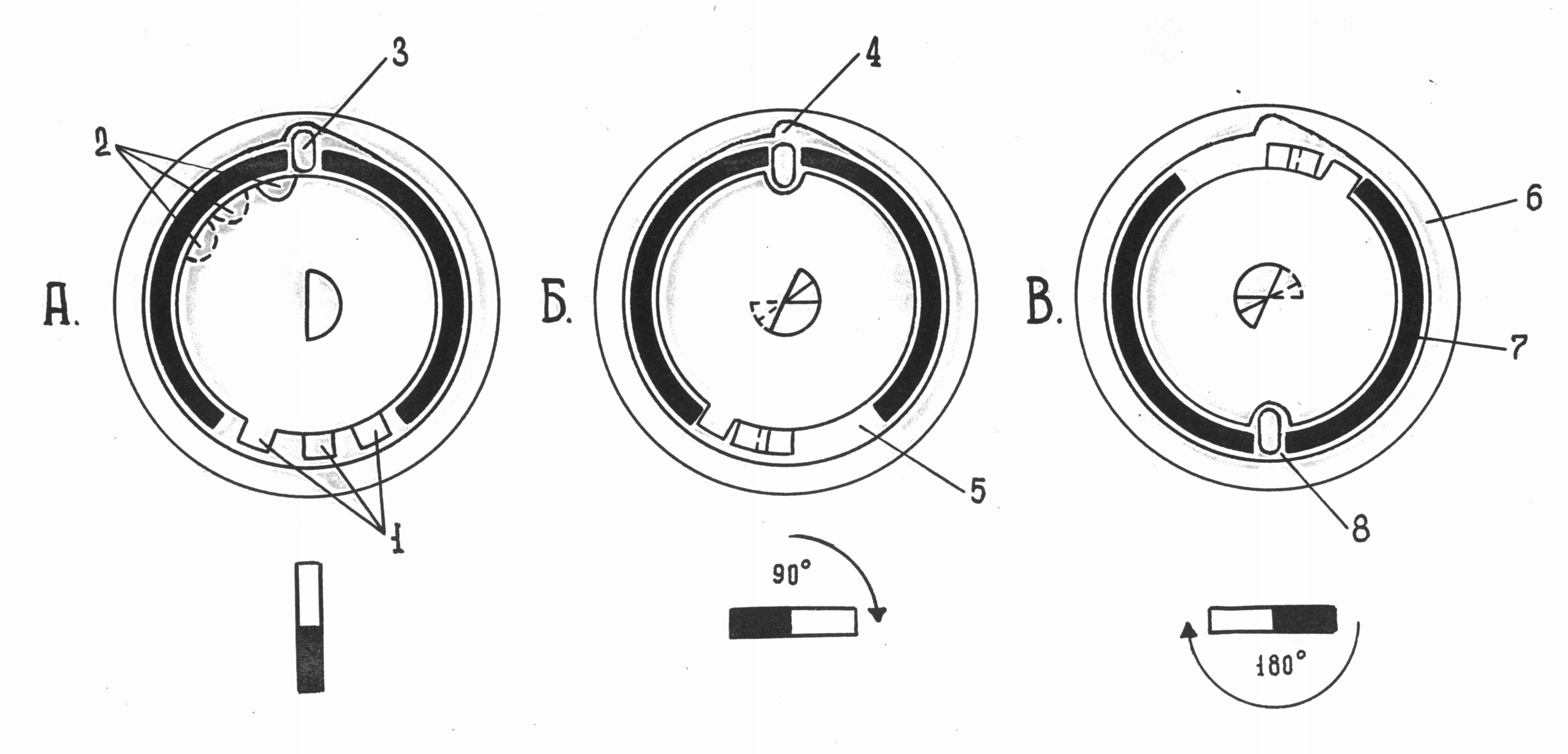
Rice. 23. The principle of operation of the locking mechanism of the lock "Abloy":
A- cylinder mechanism in the locked position; B- position of parts
Locking mechanism when the key is turned 90º; IN- cylinder
The mechanism is in the unlocked position; 1 - protrusions of the main disks;
2 - recesses of the main disks; 3 - locking pin; 4 - recess in the body
Castle; 5 - wide cutout of the lock case; 6 - body of the castle; 7 - frame
cylinder; 8 - Narrow body cutout. For better position perception
The details in the figure show only the three main discs
If the pin is spring-loaded, then it sinks into the longitudinal recess during the subsequent turn of the key. In the case when the key is turned by 90º, part of the protrusions of the main disks rests against the edge of the wide cutout of the case, and with further turn of the key (the angle varies by different types locks from 90 to 180º) turn the body of the mechanism released from fixation in the socket of the lock body. At the same time, the leash fixed on the body of the mechanism rotates and moves the deadbolt. Locking occurs in reverse order.
Many locks of this type are automatic. But even in this case, to remove the key from the lock after unlocking it, the key must be turned in the opposite direction so that the main disks and the locking pin take their original position.
Abloy locks are known, produced both for individual and for brigade keys. A batch of such locks can be used on an object with many doors (cabins on one of the decks of the ship, rooms on the same floor of the hotel, etc.). Each of the locks of the party has its own key, not suitable for other locks, and at the same time, one of the keys can unlock all the locks of the given party, not counting the lock for which it is intended. This is achieved by the presence of additional cutouts on the main disks of all locks, oriented to the location of the protrusions on the brigade key shaft.
Locks with a coded (cipher) locking system are available in two versions: without a key, as a separate product, and with a key designed to rotate bushings or discs. But in any case, the key to the lock is a numeric or alphabetic code (cipher).
Principal device one of the varieties of a padlock with an encrypted system is shown in fig. 24. The lock consists of a body, a bow with two lockable ends, on which two segment-shaped recesses are made. Four cylindrical bushings with segmented recesses are inserted into the transverse holes on the lock body. On the end surfaces of the bushings facing the lock body, there are risks, and on the surface of the body around the bushings there are certain numerical or alphabetic designations. In the locked position of the lock, the bushings enter the recesses at the ends of the shackle and hold it in the body.
Rice. 24.
A- bushings are installed in the “locked” position; B- bushings installed
In the "unlocked" position. 1 - bow; 2 - frame; 3 - bushings (bolts)
To unlock the lock, each sleeve must be turned so that the recess on it is against the recess on the shackle. To do this, knowing the digital or alphabetic code of the lock, it is necessary to set the risks against the corresponding signs on the lock body by rotating the bushings. In some locks, the outer surfaces of the bushings do not protrude above the surface of the body, and it is impossible to turn the bushings with your fingers. Therefore, a key is issued to the lock, with which the bushings are turned. In such a case, protrusions of a certain shape or diametrically located slots are made on the bushings.
Another type of padlock with a combination system is shown in fig. 25. The locking mechanism of the lock consists of a block of disks of the encrypted system connected to the lockable end of the shackle, which has several rectangular protrusions located on the same line. The number of protrusions is determined by the number of disks. The shape of the disks is glass-shaped with a round hole in the bottom and a rectangular cut extending from it. Numerical designations are applied along the perimeter of the outer surfaces of the disks. On each disc, opposite one of the numbers, there is a rectangular cutout in the bottom of the glass. The combination of these numbers is the key to this lock.
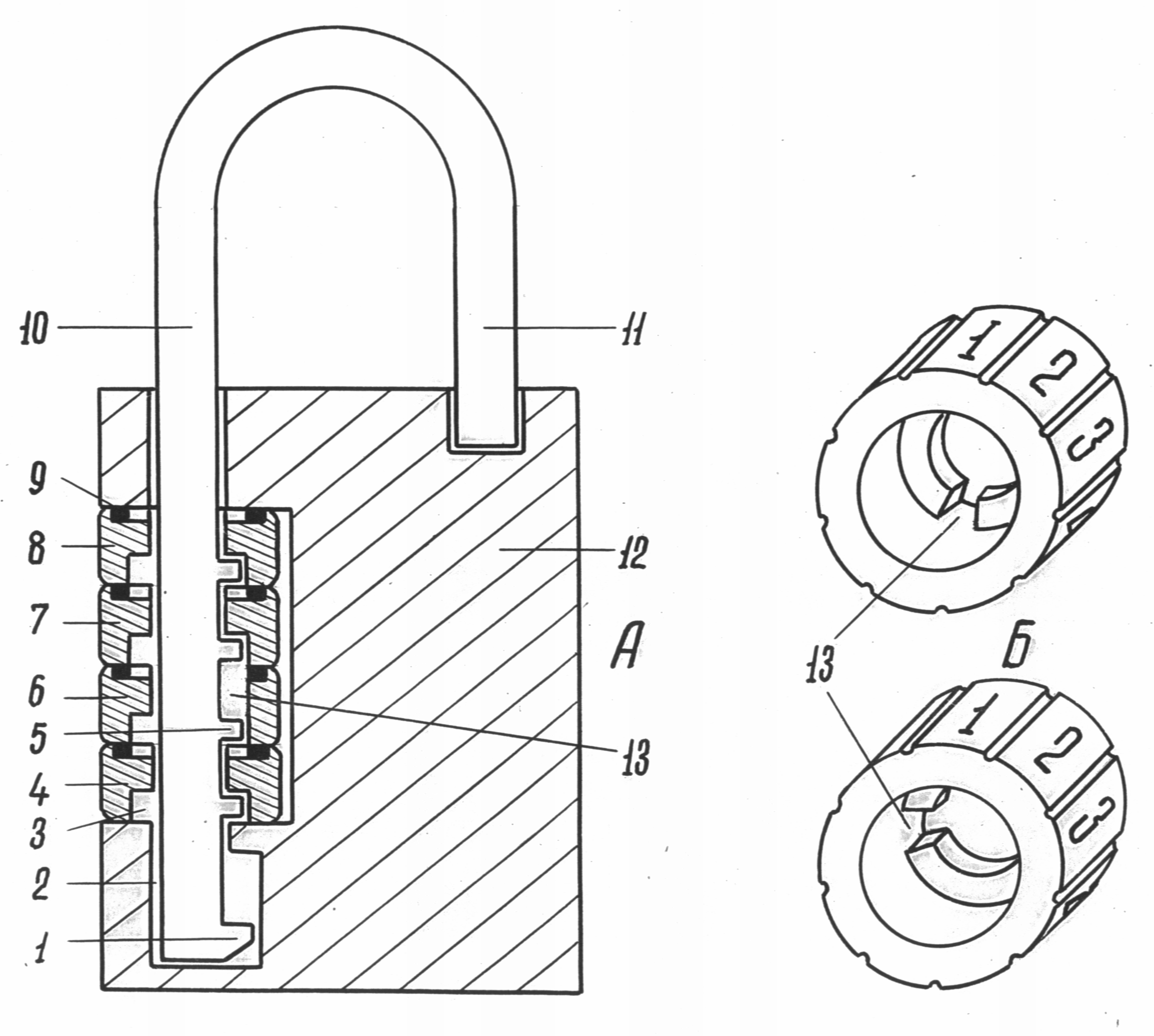
Rice. 25. Padlock device with encrypted locking system:
A- lock; B- disks; 1
- limiter; 2
- a hole for the lockable end of the shackle; 3
- an annular recess in the disk; 4, 6, 7, 8
- disks; 5
- ledge on the lockable end of the shackle; 9
- spring washer; 10
- lockable shackle end; 11
- the free end of the bow; 12
- frame; 13
- disc notch
In the locked position of the lock, both ends of the shackle are in the opening of the housing. The discs are arranged so that their rectangular cutouts do not coincide with the protrusions on the lockable end of the shackle and thereby fix it in the lock body. To unlock the lock, you need to turn the disks so that each digit of the code stands against the risks on its body. In this position, all rectangular cutouts in the discs will line up with the tabs on the lockable end of the shackle. As a result, they are able to freely pass through the disc cutouts. The shackle is pulled up until its free end comes out of the recess in the body. To prevent the disks from rotating on their own when the position of the lock changes, lamellar spring washers or spring-loaded locking balls are placed between them.
The number of possible combinations of numbers in the code of such locks depends both on the number of disks and on the number of digital or letter designations on each of them. For example, if there are 5 disks in the lock, and each of them has 6 letters (numbers) of the code, then the total number of key options for this lock will be 6 (7776).
Screw locks are relatively simple in their design and are mainly made in a hanging version. The principal device of a screw lock is shown in fig. 26. The castle consists
Rice. 26. Screw lock device:
1 - frame; 2 - a hole in the body for a deadbolt; 3 - a hole for a key;
4 - bolt shank; 5 - screw bolt; 6 - a hole in the lockable end of the shackle; 7 - bolt head; 8 - lockable shackle end; 9 - shackle
from a body, a shackle with lockable and free ends and a screw bolt. There are three holes in the lock body - two vertical for the ends of the shackle and one transverse for the deadbolt. On one of the surface areas of the hole for the bolt, a thread is cut. At the lockable end of the shackle there is a hole for the bolt head. The thickened part of the bolt is threaded, and it ends with a shank, which can have a different transverse profile and dimensions corresponding to the profile and dimensions of the recess in the key shaft. In some cases, a slot is made on the end of the shank, and then the key stem ends with a spatula resembling the working part of a screwdriver.
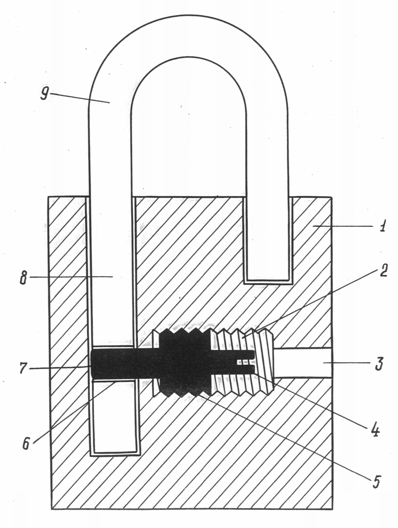
In order to hinder access to the screw bolt and prevent the possibility of visual observation of the configuration features of the shank, two round, mutually perpendicular holes of different diameters are made in the lock body, interconnected by a narrow slot (Fig. 27). In this lock, the function of the bow is performed by a metal rod with a thickening at the end. The rod is threaded into the door lining, in which it is held by a thickening. The key of such a lock has an extension at the end, and the recess in this extension corresponds in size and shape to the bolt shank. 
Rice. 27. Screw lock device:
1 - hole for the rod; 2 - bolt head; 3 - recess in the rod;
4 - rod; 5 - rod head; 6 - threaded hole for screw
Zasova; 7 - frame; 8 - key; 9 - narrow hole for a key; 10 - slot
Between keyholes; 11 - wide opening for a key;
12 - bolt shank; 13 - threaded part of the bolt
To lock the lock, the key is inserted into the wide opening of the body and moved through the slot into the narrow opening. With a recess, the key is put on the bolt shank and screwed through the threaded hole in the body until it stops. In this case, the bolt head enters the recess on the rod and fixes it in the body. To unlock the lock, the bolt is unscrewed to the stop and the bolt head releases the rod from fixation in the body.
Forensic classification of locks is carried out on the following grounds:
Hanging (removable).
Depending on the features of fastening permanent locks, they are divided into mortise and overhead. The body of the mortise lock is placed in a special recess in the door leaf, and the body of the overhead lock is attached to the surface of the object.
There are some types of rack and pinion locks that are automatically locked from the inside of the room and with a key from the outside.
6. By the type of impact of the key on the details of the locking mechanism. Locks are locked:
§ 2. Methods of unlocking and picking locks used
when committing crimes
The lock, as an obstacle, can be removed by actions such as unlocking or picking. The concepts of "unlocking the lock" and breaking the lock "are considered in forensic science in order to characterize such actions and differentiate existing ways removing locks when committing crimes.
It should be noted that GOST only gives the concept of breaking a lock as actions by which the lock is removed as an obstacle in front of the protected area. In this case, two group hacking methods are distinguished:
1. Non-destructive hacking methods: methods of influencing the lock with the help of widely used, limitedly used or specially made tools, devices, equipment that do not lead to mechanical damage and (or) loss of the lock's performance.
Among non-destructive methods, manipulations stand out - non-destructive method breaking mechanical locks using master keys and (or) other hand tools and devices used for certain types and designs of locks.
2. Destructive hacking methods: methods of influencing the lock associated with irreversible changes in its design, mechanical destruction or deformation individual elements. In this case, access to the bolt can be released or facilitated, and its movement occurs in an already destroyed or significantly weakened lock structure. After destructive influences, the lock loses its functionality.
In forensic science, a system of ways to eliminate a lock as an obstacle has long been established, in which both breaking and unlocking of locks stand out.
Picking a lock - actions by which a lock is removed as an obstacle by destroying it. If at the same time the bolt moves, then it moves in the already destroyed lock, when access to the details of the locking mechanism is released 1.
Unlocking the lock - actions directly aimed at moving the deadbolt without first destroying the lock.
There are the following methods of unlocking locks used in the commission of crimes:
If a key is made specifically for unlocking a specific lock with criminal intent, then it will be considered counterfeit with respect to that lock. Fake keys are obtained from blanks or other keys according to casts, drawings, large-scale photographs, or directly from the key complete with the lock or the number designations on it in the case when the criminal knows the number designation system adopted at the manufacturer.
If the key is selected or made to unlock a specific lock, then the master key is to unlock a series of locks of a certain design type. A variety of locking mechanisms predetermines the design features of the master keys. So, a master key for leverless locks is a metal rod, one of the ends of which is bent and acts as a beard. The barbs of the master keys for lever locks have protrusions and recesses of various heights and widths. Master keys for cylindrical locks are made of thin metal plates with a wavy bottom edge (Fig. 28, 29, 30).
Rice. 28. Lockpicks used to unlock leverless locks
Rice. 29. A set of master keys used to unlock lever locks 
Rice. thirty. Picks used to unlock cylinder locks
In expert practice, there are so-called "comb" master keys for unlocking cylinder locks. With this pick, the pins of the cylinder are completely recessed into the sockets for the pins of the body, and the cylinder is rotated (Fig. 31). The possibility of its use is mainly due to the design flaws of the locks. 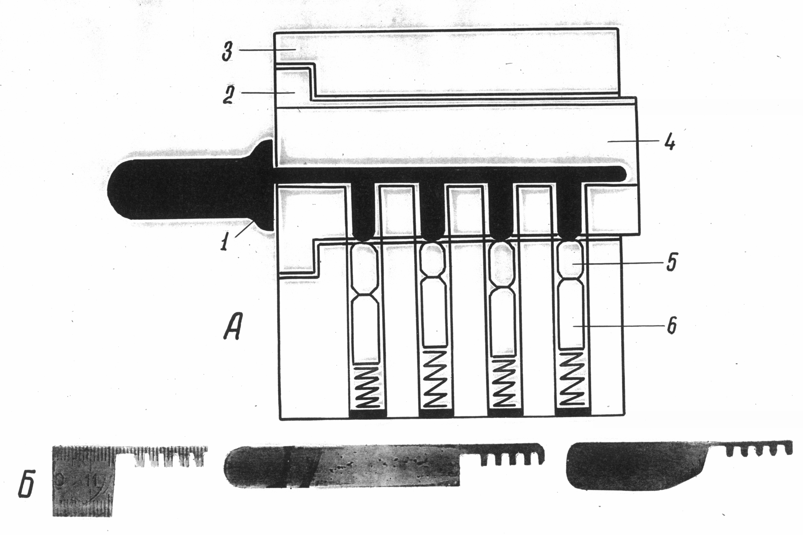
Rice. 31. Comb pick used to unlock cylinder locks:
A- the principle of operation of the comb pick: 1 - master key; 2 - cylinder;
3 - cylinder body; 4 - well for a key; 5 - cylinder pin;
6 - housing pin; B- comb picks
The originality of the design of the cylindrical mechanism of the Abloy lock and the peculiarities of its functioning predetermined the development by the criminals of a master key with a moving beard. To unlock the lock using a similar master key, a hole of small diameter is drilled in the restrictive sleeve of the cylinder mechanism housing, under the locking pin. A needle is inserted into it and the first main washer is rotated with a pick beard until the notch on it is against the needle, i.e. under the locking pin. The needle is advanced all the way into the next main washer and also rotated by moving the pick bar to the desired position until the notches on all the main washers (disks) are under the locking pin.
Released from fixation in the socket of the lock body, the locking mechanism (cylinder with its body), after removing the needle, is turned with the same master key, the beard of which acts on one, as a rule, the last of the main washers rigidly fixed in the body of the mechanism. To hide the traces of unlocking, criminals seal the hole on the body of the cylindrical mechanism with a piece of foil, the color of which is close to the color of the metal from which the case is made.
To unlock the simplest leverless locks, various foreign objects are sometimes used: a nail, wire, hair clip, etc., which are inserted into the keyhole and, by pressing on the bolt shank, move it to the required position. The deadbolt of the lock with a rack mechanism is transferred to the “unlocked” position by the method of its phased movement (with intermediate fixation) with two pointed objects inserted into the keyhole. A needle, an awl, etc. can serve as such items.
The considered methods of unlocking provide for the mandatory impact of objects used for this purpose on the details of the locking mechanism of the lock, and the process itself resembles unlocking with a standard key. Therefore, traces of the use of such items can also be located on the parts of the parts with which the standard key interacts, which in some cases does not allow establishing the fact that the lock was unlocked by a foreign object.
Wistity (tweezers for unlocking with thin, semicircular elongated ends) and tubes with a longitudinal slot (slots) are used for unlocking when a key is inserted from the inside of the lock. WITH outer side the core of the key is captured by the jaws of the tongs or a tube is put on it, after which the lock is unlocked by turning the key. Traces of the use of such tools can only be found on the shaft of the key, the base of the barbs, or on the edges of the keyhole.
Unlocking the locks by pressing the deadbolt is carried out by the action of a foreign object on the bolt head protruding beyond the lock body. Usually, permanent (mortise and overhead) locks are unlocked in this way, and most often automatic. In automatic locks of those types where the deadbolt in the locked position is fixed only by the force of the spring or the lock was locked without using a key, i.e. the deadbolt works like a latch (without fixing in the locked position), its extraction is carried out with a thin sharp object inserted between the locking and face plates. By acting on the lateral or beveled plane of the lock head, the deadbolt is pushed into the lock body. Traces of a foreign object remain only on the plane of the bolt head, front and striker bars.
When pressing the deadbolt rigidly fixed in the locked position, access to the end face of its head is preliminarily provided. To do this, cut out (cut down) a part door frame behind the lock bar. By the action of a durable object (crowbar, "crowbar", etc.) on the end face of the bolt head, it is pushed into the lock body. As a result, significant deformations occur in the locking mechanism, and sometimes breakage of individual parts that fix the deadbolt.
Practice knows cases of unlocking cylinder locks without the impact of foreign objects on the cylinder pins. To do this, a viscous mass is introduced into the keyhole (solid oil, petroleum jelly, thick oils mixed with fine dust). With repeated locking and unlocking of the lock with a standard key, this mass penetrates into the sockets of the cylinder and body pins and, having thickened, fixes them in the position that they occupy when the complete key is inserted into the keyhole. In the locked position of the bolt, the cylinder is not fixed in the housing and can be turned by a foreign object without affecting the pins.
Methods for breaking locks are also varied and are determined not only by the design features of the locking mechanisms, but also by the method of attaching locks to objects. Most common the following types hack:
Used to cut the bow various tools and mechanisms: hacksaws, files, gas-cutting devices, etc. The free end of the bow is cut or locked if there is no free end in the lock. The place of cutting the shackle is determined both by the design and the features of the devices for hanging the lock (door hinges, rings, etc.). The shackle is cut, as a rule, from the side of the side face of the lock body, since this position is most convenient.
When breaking control locks, a solid object, such as a screwdriver shaft, is inserted into the space between the additional cover and the upper face of the housing at the free end of the shackle, and the face of the housing is pressed down. Since in locks of this type the free end of the shackle enters the case to a small depth, as a result of pressing it is between the upper face of the case and the control cover. By turning the control cover and, together with it, the shackle around the lockable end, it is released from fixation with a deadbolt, and the free end comes out of the hole in the additional cover.
Cylinder locks can be broken by drilling a part of the cylinder mechanism to release the cylinder from fixation in the body. Drilling is carried out in the body along the line of pins to the entire depth of their location. A part of the body and pins under the cylinder is drilled, as a result of which, without removing the drill, the cylinder can be turned with a foreign object.
Features of hacking by the method of destruction of the lock body are determined by the fastening of the lock to the object. For padlocks, the cover is separated after drilling out the heads of the fastening posts. When breaking a mortise lock, a part of the door surface is preliminarily cut out at its location and the cover is separated, gaining access to the locking mechanism.
Breaking of the cylinder mechanism of a double-sided mortise lock is carried out using specially made devices. A lever device having a recess at one end, similar in shape and size to the profile of the body of the locking mechanism, is put on the body and pressed down with force. In this case, the body breaks at the location threaded hole for fixing screw. The broken off part of the body is removed, and the bolt is moved through the hole in the body of the lock.
Rim locks with a cylinder mechanism are also broken by striking the end of the case and cylinder or an object inserted into the key hole. The body of the lock is completely or partially separated from the door, and the head of the deadbolt comes out of the cutout in the striker plate.
In mortise locks of the Abloy type, the cone-shaped body, in which the cylinder mechanism is placed, is attached from the outside with two screws to the lock body. Hacking such locks is carried out with the help of a crowbar, “crowbar”, etc. By prying off the body with a cylinder mechanism and acting as a lever, they tear it off the lock body. A bolt is moved through the hole in the door. Due to the tight fit of the mechanism body to the door, a recess is preliminarily cut out under it, where the tool used for hacking is inserted.
In addition, Abloy locks are broken by turning the locking mechanism using a high-strength metal rod inserted into the keyhole. Using devices to increase the lever, the cylinder and body are rotated until the bolt completely exits the hole in the strike plate. In this case, the edges of the cutouts on the main discs and the locking pin shaft are partially cut off.
The use of explosives to destroy locks is rare in practice. An explosive is poured into the lock body, and a igniter cord is inserted into the keyhole, which is then set on fire. To prevent the explosive from spilling out of the case, the holes in the lock are closed with plasticine, wax, etc. The explosion destroys the lock completely or to such an extent that access to the details of the locking mechanism becomes possible.
§ 3. Investigation of traces of unlocking and breaking
locks at the scene
A preliminary study of traces of break-in and unlocking of locks helps to obtain information directly at the scene about the circumstances and method of committing a crime, the type, type of burglary weapon, the criminal “qualification” of the burglar, the temporal characteristics of hacking or unlocking, etc.
It is carried out by methods that exclude the possibility of change appearance lock, moving its main parts or parts of the locking mechanism.
Signs of criminal unlocking of locks, as a rule, are located inside their cases, and therefore their detection during a preliminary study during an inspection of the scene is unlikely. The exception is cases of detecting traces in the form of scratches, scrapings and metal shifts on the edges of the keyhole or in its immediate vicinity.
Traces of burglary can be found both directly on the lock itself, and on the elements and devices for attaching it to the door.
Picking padlocks is most often done by tearing, sawing, cutting or biting its shackle. Breaking mortise locks is characterized by the destruction (knocking out, breaking or drilling) of its cylinder mechanism or the destruction of the body, which, as a rule, is accompanied by extensive destruction of the door area adjacent to the lock.
If traces of sawing or drilling are found, it is necessary to remove the sawdust (chips) formed during this. To do this, it is most convenient to use any portable permanent magnet.
Mandatory fixation is subject to traces of breaking not only on the lock itself, but also on the door, devices for hanging the lock. It is also necessary to record the design features of the door (the number of door panels, the presence and size of the gap between the door and the door frame, the tightness of the door, the presence of a flashing, etc.), defects and damage to the door. The above can play a role in resolving questions about the power characteristics of hacking, the type and type of hacking tools, and the physical data of the person who committed the hacking.
In cases where multiple traces of hacking tools are found, it is advisable, in addition to photographing them, to draw diagrams and plans for their location.
Absolutely unacceptable are any experimental actions to unlock (lock) the locks, both with their regular keys, and with master keys and random objects found at the scene.
The main task of the preliminary study of traces of hacking is to establish the group affiliation of the hacking tool. According to the traces of the cut (notched), its appearance can be established ( hacksaw blade, twisted wire saw, file, "grinder"), dimensional characteristics and shape (width of the blade or disk, profile and notch size of the file or file). The shape and size of sawdust allow you to determine the geometric parameters and the degree of sharpness cutting elements tools used for hacking.
A preliminary study of drilling marks solves interrelated tasks: establishing the shape, dimensional characteristics of the drill and establishing the type of tool (mechanical or electric drill). To do this, it is necessary to investigate the entire system of traces that occur during drilling: through and non-through traces, chips, finite elements formed when the drill leaves the barrier.
The study of static traces of pulling out the bow or wringing establishes the characteristics of the working part of the tool (hacking tool): dimensions, shape, contour configuration, the presence of catchy signs, which, in turn, allows us to determine its design, name and scope of use in domestic or industrial activities. The latter is essential for establishing the circle of persons involved in working with him.
Conclusions and assumptions made by a forensic specialist based on the results of a preliminary study serve to solve operational search problems, plan and organize investigative actions, but cannot have evidentiary value.
preliminary study specified objects carried out in full accordance with the methodology of similar studies of traces of hacking tools.
§ 4. Methods of trace examination of locks
In the traceological examination of locks, the direct objects of research are material changes that have arisen as a result of criminal unlocking or breaking locks, i.e., signs of the impact on locks of foreign objects (forged and picked keys, master keys, random objects, breaking tools).
All signs of exposure to foreign objects can be divided into three groups:
1. Traces-displays of the contact parts of foreign objects both on the outer surfaces of the locks and inside them on the details of the locking mechanism.
2. Deformations, breakages, disconnections and intermediate positions of parts of the locking mechanism of locks.
3. Objects and substances that are not typical for a lock of this constructive type: parts of master keys, random objects, particles of impression masses, etc.
The general scheme of the traceological examination of locks can be represented as a sequence of the following stages:
A) familiarization with the research materials;
B) examination of the outer surfaces of the lock and keys;
C) dismantling the lock;
D) study of the locking mechanism as a whole and its details;
D) expert experiment;
E) evaluation of the results of the study and the formation of conclusions.
Compliance with this sequence of stages is an indispensable condition for a complete and objective study of castles. Consider the content of the expert's activity at each stage in solving the three most common questions in expert practice:
1. Establishing the technical condition (serviceability) of the lock.
2. Establishing the fact that the lock was unlocked by a foreign object. (In a trace examination, it is customary to consider any object other than a standard key, i.e., the key included in the lock kit, to be outsiders: fake and picked up keys, master keys, wisties, random objects (hairpins, knitting needles, nails, etc.).
3. Establishing the fact of breaking the lock.
The sequence of actions of the expert at the first stage of the study practically depends little on the questions posed. The main and main task in this case is to establish the possibility and expediency of conducting an examination on the basis of the materials submitted for the study.
Particular attention should be paid to the completeness and sufficiency of information about the circumstances of the crime, the conditions of operation, detection and seizure of the lock: the duration and intensity of unlocking and locking the lock, the method and devices for securing the lock, the presence, nature and localization of traces of hacking tools on objects the material situation of the scene, the presence of negative circumstances and signs, etc.
When getting acquainted with the questions posed to the expert, it is necessary to make sure that the basic terms and concepts of trace examination of locks are unambiguously interpreted by the person who appointed the examination and the expert conducting it. Most often this concerns the concepts of the health of the lock and the fact of its unlocking by a foreign object.
It is necessary to distinguish between the concepts of “serviceability of the lock” and “the possibility of its operation for its intended purpose”. The latter is also possible with a technically faulty lock, for example, if it lacks one lever or a pair of cylinder mechanism pins.
Under the criminal unlocking of the lock should be understood finished action that causes the bolt to move to the unlocked position. Therefore, the correct formulation of this question should be considered as follows: was the lock unlocked by a foreign object? All other editions of such a question do not have the proper degree of specificity. After reviewing the questions, in case of their discrepancy, the expert must, in agreement with the investigator, correct their wording, bringing it to a form that provides a uniform interpretation.
Solving the issue of the fact of breaking the lock implies the mandatory establishment of the method and tool of breaking, as well as the state of the lock at the time of breaking: locked for one or two turns of the key; in locked but unhinged position; in unlocked state. The last two cases occur when hacking is simulated.
At the second stage, the main goal is to study the general condition of the lock, the position of its deadbolt, detect signs of foreign objects on its outer surfaces, study the keys and establish their identity and the correspondence of the shape and size of their barbs (rods) to the corresponding characteristics of the key hole. The latter is achieved by comparing the corresponding dimensional and design parameters. The introduction of the key into the lock well is completely unacceptable.
If traces of fingers or impositions of any foreign substances are found on the outer surfaces of the lock, they should be preserved for the purpose of fingerprinting, physical, chemical or biological examination. Further examination of the outer surfaces of the castle is carried out only after the specified requirement is met.
The study is carried out using additional sources of oblique and diffuse illumination, a magnifying glass or microscope MBS-1,2,9 with a total magnification of about 4-16 times. General form objects of study (lock, keys, unlocking or breaking tools), as well as all detected signs of the impact of foreign objects are recorded according to the rules of large-scale photography.
In the case of submission for examination of alleged hacking or unlocking tools, they are examined in accordance with the methods adopted in the trace examination for solving both diagnostic and identification issues.
The third stage involves the complete disassembly of the castle. Depending on its design, one of the following disassembly methods is used: unscrewing the screws securing the housing cover; sawing, cutting, grinding or drilling of rivet racks; drilling locking pins; flaring or sawing of the lock body. When examining cylinder locks or Abloy locks, their cylinder mechanisms must be previously separated from the lock body.
Regardless of the method of disassembly, the following conditions must be strictly observed:
A) comply with safety requirements, especially when working on machines;
B) to disassemble the lock body with the least possible damage and deformation;
C) when disassembling the locking mechanism, all its parts of the same type (levers, pins, pin springs, etc.) must be marked with numbers, observing their sequence;
D) the assembly of the locking mechanism is carried out in the sequence strictly reverse to its disassembly;
E) in order to prevent chips or sawdust from getting inside the lock, the hole for the key is sealed with adhesive plaster, electrical tape, adhesive tape and other materials.
At the next stage, the locking mechanism of the lock is carefully and consistently studied. After separating the cover of the case (box) of the lock, the position of the mechanism as a whole and the relative position of its mating parts (bolt and lever, bolt and cylinder leash, etc.) are photographed, since in some cases it is this that serves as the basis for the conclusion about the fact of criminal unlocking of the lock .
In order to detect deformations or the presence of traces of foreign objects, every detail of the locking mechanism is carefully examined. After fixing the presence and location of particles of substances and objects that are not typical for a lock of this constructive type, they are removed and their safety is ensured for possible other forensic examinations.
An expert experiment is carried out mainly when solving diagnostic issues: establishing the possibility of unlocking the lock with a specific foreign object or key submitted for examination; establishing the technical condition (serviceability or malfunction) of the lock; establishing the position of the locking mechanism of the lock at the time of breaking the latter; the presence of a causal relationship between the intermediate position of the parts of the locking mechanism and the impact of a foreign object on it, etc.
To formulate objective, reliable and reasonable conclusions, the expert is obliged to analyze all the revealed factual data: the presence, mechanism of formation and localization of signs of exposure to foreign objects; the condition of the lock as a whole and its locking mechanism; the relative position of the details of the latter, etc. The next step in the formation of conclusions is the construction of a logically verified chain, the links of which will be all the facts revealed during the study. To do this, the reasons for the occurrence of certain signs must be established and explained, their connection with the criminal impact on the castle must be established; discrepancies and revealed negative facts should be explained.
The order and sequence of synthesizing the information obtained in the course of the study depends on the nature and content of the issue being resolved by the expert.
The last stage is the preparation of a written opinion and the production of a photo table. The structure of the conclusion of the examination of locks is no different from the conclusions of other traceological examinations.
Establishing the health (malfunction) of the lock
The concept of "serviceability" characterizes the state of the lock, which ensures its unlocking and locking with a regular key in full accordance with the design. The necessary conditions for this are: the integrity of the body and the absence of holes and gaps in it, allowing you to act on the deadbolt, bypassing the key hole; the presence in the lock of all parts of the locking mechanism; the absence of their breakdowns, deformations, their correct pairing; reliable fixation of the bolt of the lock in its locked position.
All these facts are established by an expert when examining both the outer surfaces of the lock and after disassembling it. Subject to the specified conditions, an expert experiment on unlocking and locking the lock with a standard key is carried out. Necessary condition recognition of the lock as serviceable are the failure-free interaction of the parts of its mechanism in the process of unlocking and locking and reliable fixation of the deadbolt in the locked position.
When examining leverless locks, such an experiment is possible regardless of whether a complete key is submitted for research or not. The simplicity of the design of such locks, a small number of moving parts of the locking mechanism allows you to check their interaction "by hand", visually observing the result of the experiment.
A similar technique is also applicable in the study of general-purpose lever locks, which are relatively simple in design. In the absence of a complete key, it is also possible to select or make a prototype key, under the influence of which a reliable interaction of the parts of the locking mechanism occurs. This fact should be reflected in the conclusion, with an obligatory illustration using a diagram (drawing), which indicates the shape and dimensions of the rod and key bit.
In the study of cylinder locks, their cylinder mechanism is first separated from the body, and then an experiment is carried out on the interaction of the key and the cylinder mechanism. Turning the cylinder with a key indicates only the possibility of using the lock for its intended purpose, but cannot serve as a basis for concluding that it is in good condition. To form the final conclusion, the interaction of the cylinder mechanism and the details of the locking mechanism, driven by its leash, is checked.
A preliminary judgment about a malfunction, regardless of the design type of the lock, can be made already when examining its external surfaces, in case of detection of its significant deformations and damages that preclude normal operation. As a rule, this applies to padlocks. Most often, damage and deformation are presented in the form of:
A) deformation of the bow, which consists in the misalignment of its lockable end and the hole for it, located in the upper face of the box;
B) separation (absence) of the lockable end of the bow;
C) deformation or complete cutting of the axis of the bow;
D) deformation or destruction of the box.
In mortise locks, the signs of their failure are the destruction of the body, the separation (or breaking) of the cylinder mechanism from it, the deformation of the deadbolt head, which excludes the interaction of its head with the hole in the striker plate, etc.
However, in any case, despite the discovery of the listed defects, the final conclusion about technical condition the lock is possible only after its complete disassembly and a thorough examination of all the details, since in addition to establishing the fact of a malfunction (healthiness) of the lock, it is necessary to indicate its specific manifestation, as well as to establish the cause. The causes of the malfunction may be:
Criminal unlocking or lockpicking;
Violation technological process its manufacture;
Long-term operation of the lock.
The characteristic consequences of burglary, which appear on the details of the locking mechanism, are deformation or breakage of the axis of the levers, the deadbolt rack, the springs (springs) of the levers; deformation or breakage of the leashes of the cylinder mechanism, shearing of locking pins, etc. Simultaneous breakage or deformation of several mating parts that perceive the force developed by the hacking tool is possible.
Violation of manufacturing technology is manifested most often in the presence of gaps on the lock body between its constituent elements, the dimensions of which exceed the specified design requirements; in the separation of the levers and their springs or the separation of the deadbolt and its rack, which is the result of their poor-quality pressing; in the breakage of springs, the lever that occurs as a result of a violation of the mode of their heat treatment (hardening), etc.
As a result of long-term operation of the lock, at the same time, wear occurs on parts of the parts that actively interact in the process of unlocking and locking: the deadbolt rack and the edges of the cutouts in the lever windows, the cylinder leash and the cutouts on the bolt, the cylinder pins and the surface of the cylinder mechanism housing, etc.
In substantiating the conclusion about the technical condition of the castle, all the necessary factual data established during the study should be indicated. An approximate wording of the conclusion about the health of the lock can be as follows:
"The presence of all parts of the lock mechanism, their correct pairing, reliable interaction during the expert experiment, including fixing the deadbolt in the locked position, serve as a sufficient basis for concluding that the lock submitted for research is in good condition."
There may be cases of detection in the lock of defects that reduce the level of security properties of the lock, but still ensure its locking. Most often, these are the absence of individual parts: levers, lever springs or pins. In such cases, the following conclusion is formulated: “The absence of one lever (pin, spring of the lever) allows the lock to be used for its intended purpose, but significantly reduces the level of its security properties, which serves as the basis for a conclusion about the malfunction of the lock.”
If significant breakdowns and defects are found, the following conclusion is formulated: “Deformations of the deadbolt stand and the axis of the levers, which arose as a result of breaking the lock by pressing the deadbolt, exclude the interaction of the parts of the locking mechanism (moving and fixing the deadbolt), which serves as a sufficient basis for concluding that the lock is malfunctioning and the impossibility its use for its intended purpose, i.e. exploitation”.
A locksmith or a locksmith salesman often has to deal with philistine myths and legends regarding the subject of our work. And the emergence of such myths and legends in most cases is associated with low literacy, both consumers and many sellers. A person does not own the topic, and in order to explain some incomprehensible moment, he has to apply fantasy, which often borders on stupidity.
Here we will talk with you about lever locks. Let's consider their structure, as well as discuss the legends and absurdities that surround the level castle.
Locks with keys of this type are called suvalnye, and not suvalnye, as some call them.
From the word "suvalda", and not from the verb "suvat". We will talk about the origin of this unusual name below.
Lever type locks are among the most ancient in the world. In one of the previous materials, where we considered general information on castles, there was an introductory part about the Egyptian castle, which appeared about 4000 years ago. So, despite the fact that the code elements of the Egyptian lock were pins, according to the principle of operation, it is more like a lever lock, because the bolt was controlled directly by the key, and not by some kind of drive elements. And the Egyptian castle is the first official mention of castles in the world.

Sometimes lever locks are called safe locks. It is not clear who was the first to use this incorrect definition: cunning sellers who, using the word “safe”, wanted to emphasize the secrecy of the goods being sold, or ordinary people who hoped that Magic word"safe" will raise their castles to the rank of inaccessible.
A safe lock is called a safe lock because it is designed to be used only on a safe. It is extremely difficult to install a safe lock on an apartment door or anywhere else except for a safe door. And if you contrive and install, then it is impossible to use it. The safe lock means opening and closing only from the outside. Even if some kind of “babayka” gets inside the safe, it should not be able to open the lock from the inside.

Once again, a safe lock is not one that has a certain type of mechanism, but one that is designed to be installed and operated on the safe door. There are safe locks with a lever type of mechanism. But not all lever locks are safe. We are with you within this material we are talking about apartment locks with a lever type of mechanism, and they are not safe. It is wrong to talk about some kind of security with respect to these locks.
We will study the lock with a lever type of mechanism in detail. We will take a closer look at each component, find out the purpose of each detail, and only after that we will assemble the lever lock and through the transparent cover we will see the principle of operation of the lever lock.
Like any other lock, the lever lock has a body. The case, roughly speaking, is a metal box in which all the components of the castle are placed and work. For the most part, the case is closed with a lid, as in our case.
But there are lever locks in which there is no cover, and the package of code elements is pressed and held in the case by a metal sheet, the base of the door on which the lock is mounted. This is more common on safes and metal boxes.
In some cases, the lever lock cover is made of heat-treated steel. Such locks better resist force opening methods, but the cost of a lock with such a cover, of course, increases.
In our case, the lever lock has a non-heat-treated body and cover, which are galvanized.
Direct locking of a door is carried out by a deadbolt of the lock. In a lever lock, the bolt in most cases looks like this:
The pins, fingers and plates that come out of the body are a crossbar or a crossbar, if there are several of them. It is the crossbars that fix the door leaf.
In addition to the visible part, the lock in particular and the lever lock has a hidden part of the bolt, which cannot be seen without disassembling the lock.
In particular, this is the bolt shank. The shank is a steel plate that is fixedly connected to the crossbars.
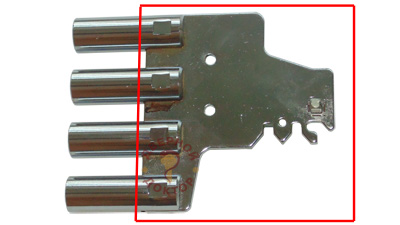
There are several important locations on the liner:
Through it, the key of the lever lock moves the bolt.
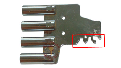
Literally 8-10 years ago, there was such a type of hacking a lever lock as opening with a roll.
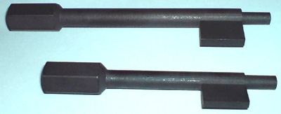
The so-called pre-made "fold" was inserted into the well of the lever lock. For the time being, the roll very much resembled the key of a lever lock, only there were no cloves on it. The roll was made of very hard alloys, hardened steel of certain grades, etc. With the help of a lever that was attached to the handle, the roll with great effort scrolled in the lever lock, broke the levers and forcibly moved the bolt of the lock. Moved just through the toothed comb. The hacking method was very fast and relatively quiet.
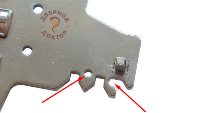
But about ten years ago, manufacturers introduced an elegant solution into their locks, which gave 100% protection against opening a lever lock with a roll. Artificially weakened toothed comb. On the lock presented by us, it can be seen that the lock tooth is artificially weakened by a drilled hole.
Now, when you try to open such a lock with a roll, the weakened tooth will break and will not let the attacker inside. True, after that the lock will no longer open with the native key, but that is another question. He coped with his main task - he did not let the crook inside.
With the introduction of an artificially weakened toothed comb, the method of opening the lever lock with a bundle disappeared completely. If ten years ago this was often talked about, and law enforcement officers often met broken lever locks with a roll. That doesn't happen anymore today.
A little off topic, let's continue to consider the deadbolt of the castle.
In addition to the toothed comb, the bolt shank has such important detail, like a deadbolt shank stand. We especially draw your attention to this detail and repeat its name: the bar of the deadbolt shank.
In our case, here it is:
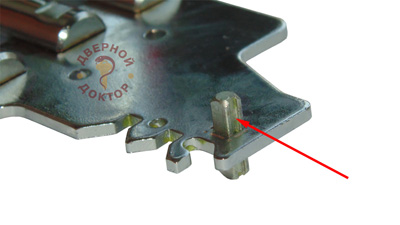
The deadbolt shank post is the part by which the deadbolt of the lock is locked. If, on a fully closed lock, you press on the crossbar, trying to drive them inside with your hand, then it is the stand that will interfere with the movement of the bolt, it will rest against the code elements.
There is such a method of opening lever locks as removing the stand of the deadbolt shank by drilling. If you climb on the Internet, you can even dig up some templates that show the exact location of the rack on a closed lock, if you center the template on the keyhole.
Drilling a rack, both earlier and now, is a very popular method of opening lever locks in a criminal environment. Therefore, many manufacturers by default make the rack from hard alloys (for example, hardened steel), or introduce something rigid into its body, such as a steel ball. You can even further protect this important element lever lock with an armored plate.
Some individuals, having gathered “tops” from the Internet about drilling, begin to convince others (and us sellers, we are the most stupid, we don’t know anything about our product, we just wait for someone to come and tell) that locks are completely useless products, because they are easily, quickly and relatively quietly drilled. In this case, we usually ask - what and when was the last time a person drilled and held a power tool in his hands? In half the cases, it turns out that the sofa opener standing in front of you does not have a drill or a “shurik” as such at all.
The specialists of our company have repeatedly had to use the method of drilling the rack in case of emergency opening of the door, in case of loss of keys or in case of breakage of the lock. We assert with confidence that opening the lock using the point drilling method is a hemorrhoid and difficult task. When drilling out the bolt shank stand, the bolt can be stuck for a very long time - you can dig up to two hours on a call. At the same time, the drilling of the shank stand is a difficultly predictable process. When drilling, the lock can get very clogged, chips can form at the drilling site, which will continue to lock the deadbolt, in the end, the deadbolt can warp, because in some models of locks, the movement of the deadbolt is positioned along the rack. There were cases when drilled hole a drill broke, those who drilled two objects superimposed on a horizontal plane know that this happens. And now it will take some time to crush the broken drill and pull it out of the hole, and only then continue drilling.
In short, the process is incredibly hemorrhoids. Of course, with experience and with an increase in the number of drilled locks, the time for this action also decreases.
But those people who professionally provide services for emergency opening of locks and doors have moved away from drilling in the direction of other types of opening, also because drilling is long, hard and poorly predictable.
The bolt shank stand is in most cases made in the form of a square. But there are a variety of forms of racks. For example, in some domestic locks, the rack can be round in cross section - this shape simplifies the opening of the lock by intellectual methods, master keys.
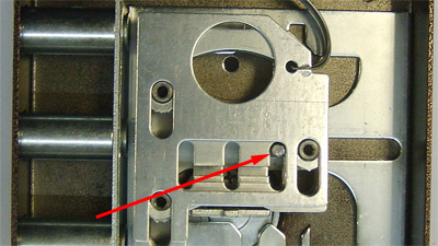
In most cases, the bolt shank stand has an anti-pick design. In our case, we see that the stand has an anti-pick slot. How it works, we will see further.
On the locks of the heavy series, where there are exits for the vertical drive (under the rods), the bolt shank often has a control detail for the exits under the rods. This is not the case in our example.
Well, now about the code elements!
Code elements of lever locks are plates different forms and are called suvalds.
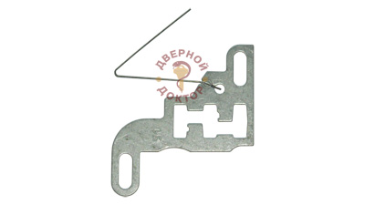
One theory claims that the word "lever" comes from the German word Zuhaltung, which translates as blocking or locking. And the code element itself in German sounds like Zuhalt. In our country, this word has somewhat transformed and turned into the word "tsugal", which is now extremely rare.
There are a fairly large number of types of levers. They may differ from each other in shape, material used, method of movement, thickness, dimensions, method of anti-corrosion treatment, etc. But all levers now and earlier have a very similar structure, and also have the same functions.
Roughly speaking, the lever is a metal plate of a certain shape with some holes.
Let's pay attention to the code labyrinth of the lever.
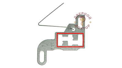
It is here that the stand of the deadbolt shank walks and dances as it moves. We will see this with you later.
The code labyrinth is formed by code ledges.
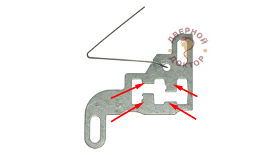
The stand of the bolt shank rests against them when they try to open the lock with the wrong key, when they hammer the bolt from the end. It is about the code ledges of the lever that the stand of the bolt shank rubs when they try to open the lock with master keys.
The distance between the code protrusions is called the code groove. It can also be called a "through groove".
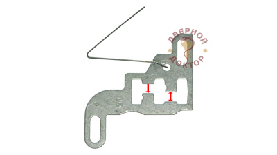
The code groove is the distance or gap between the edges of the tops of the code protrusions. It is through the code groove that the rack passes, and with it the bolt when the lock is opened or closed with the correct key.
The more accurate the lock, the smaller the code slot of this lock, the more difficult it is to open intellectually. In a high-quality lever lock, the code groove is 0.4 - 0.6 mm thicker than the thickness of the deadbolt shank stand.
The code groove is extremely rarely made with a smaller gap relative to the rack. Because after some time, the key with which you open or close the lock will wear out a little. If the gap between the rack and the coded protrusions is completely miserable, then the native keys will stop working in the lock very, very soon, for example, after 5,000 opening and closing cycles. And for the average family, this is very, very little. In other words, the size of the gap determines not only the secrecy of the lever lock, but also, to some extent, the service life.
The specialists of our company quite often have to go to the emergency opening of safes, in case of loss of all keys. And quite often come across safes of the Soviet era with old ugly lever locks.
These are supposedly one and a half meter fireproof cabinets that weigh three hundred kilograms. Lever locks on these safes worked for 50-60 years (safes began to be produced in the post-war period). And they will last for many more years.
Why?
Just because the code groove in comparison with the thickness of the rack is several millimeters larger.
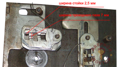
Yes, such a castle can work for 200 years. But what is its downside? The fact that without damage, with very little experience and some tool, it opens in seconds in the literal sense of the word. That is, due to the huge gap, the lock has very low protection even from the simplest intellectual types of opening.
In fairness, it should be noted that such ugly locks are no longer produced today.
But back to our levers.
As you can see, the code protrusions can contain the so-called "anti-pick slots". They represent some kind of recess or recess.
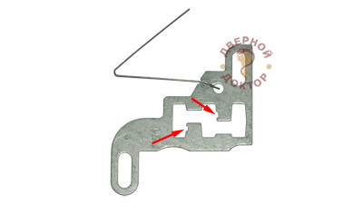
The reciprocal anti-pick groove is present on the stand of the deadbolt shank.
They work or catch each other in the following way.
As mentioned earlier, if you try to push the bolt into the lock body, it will rest against the code ledges through the rack. That is, between the stand of the bolt shank and the code protrusions of the levers, friction forces will arise. With an intelligent opening, the task is to set the lever in such a way that the through groove stands exactly opposite the rack, that is, so that the code protrusions stop blocking the deadbolt. And for this, we need to raise the lever.
But when lifting the lever, at some point, it will happen when the groove of the deadbolt shank stand falls into the anti-unlock groove of the code ledge and the further movement of the lever will thereby be blocked.
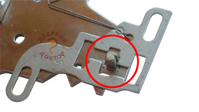
Here is a rather elegant and low-cost solution.
Today, anti-pick grooves of this type are found on most lever locks of domestic and foreign production.
According to the method of movement, there are two types of levers, the so-called swinging type ...
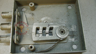
... and translational plane-parallel type.
In our case, levers are just the second type. Under the action of the key, it moves along the uprights of the housing within the grooved holes.
In most cases, levers are loaded with spring force. The spring is needed in order to return the lever to its original position, resetting the dialed code.
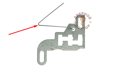
In most modern locks, each lever has its own separate spring. Sometimes a wire spring is used, as in our case. That is, the spring is a hardened steel wire bent into a certain shape. Some locks use coil springs that are inserted into a separate block.
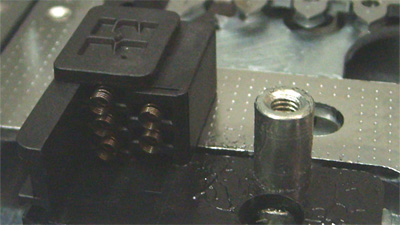
In a small percentage of locks, the so-called "tape" springs have been and are used, which simultaneously loads all existing levers.
In terms of operation, the shape of the lever of great importance it does not, as long as it is mechanically correctly designed and suitable materials are used in its manufacture.
And the variety of forms of lever springs is rather associated with the production features of a particular manufacturer and with the design features of a particular model.
Well, let's consider, perhaps, the last important dislocation of the code element - the key window and the working edge.
Each of you probably already understood that the movement of the lever is carried out by the key. So the place where the key touches when turning on the lever is called the "working edge".
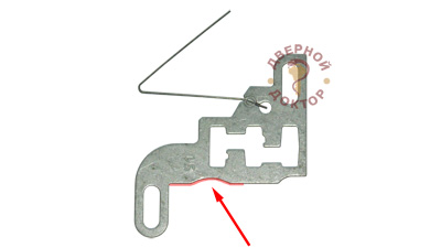
And that space, near the lever, where the key turns, is called the “key window”.
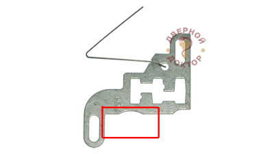
There is nothing interesting in the working edge of the lever. Its form depends on design feature specific model.
But the key window is of two types: open and closed.
On the levers of the castle, which we are now considering, is an open key window.
But in this image:
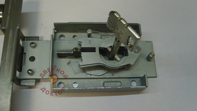
the key window is closed. And in this case, pay attention, when turning the key, it works with both beards.
OK it's all over Now. The most complex element of the lever lock is considered.
It remains a little bit and we will start assembling it!
The last component of the lever lock that we need to consider is, of course, the key.
The lever lock has a characteristic key. Some call it "safe", some "butterfly". Neither one nor the other is right, well, God bless him.
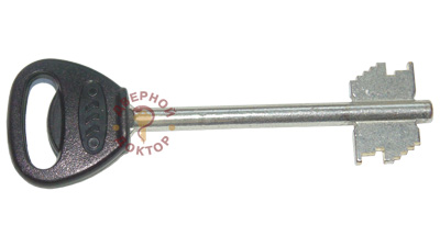
The key of a lever lock in most cases is made of brass, much less often of steel or aluminum alloys.
The key of a lever lock, like any other, has a head, or head, for which we hold when we open the lock with it. Often the name of the lock or the manufacturer's factory is located here, sometimes the logo is also located.
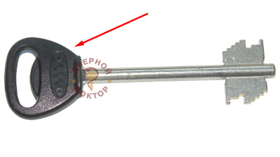
In some cases, the shape of the head is patented and used by some manufacturer under a patent. This means that other lock manufacturers are not allowed to use keys with the same head shape for their locks.
The lever wrench has a fairly long stem.
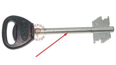
It is needed not only in order to deliver the working part to the lock case (after all, the levers are in the case, and the case itself is hidden in the door - you need to somehow reach the code mechanism ...), but also in order to position the key along the keyhole . The height of the secret of the key is measured and projected in the lever lock exactly from the center of the rod, which in turn is positioned along the keyhole.
The most important part of the lever key, its working part, is the barbs.
![]()
There are single-bit and double-bit keys.
The beard of the lever key contains a drive tooth, or the place by which the bolt moves. In our example, the drive tooth is contained in the middle of the key bit. And of course, the drive tooth is contained on both barbs - the bolt must be moved with each half-turn.
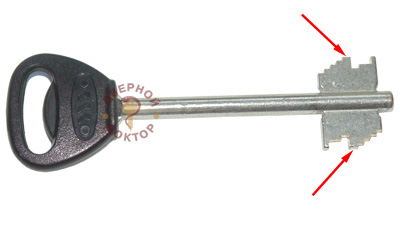
In addition to the drive tooth, the key bit contains the height of the secret. Each height of the secret interacts in the castle with one specific lever, raising it at each half-turn to the required height.
In the lock we are considering, there are 8 code elements, eight levers. They are located on opposite sides of the bolt shank. Therefore, the beard of the lever key has the following structure with respect to the mechanism.
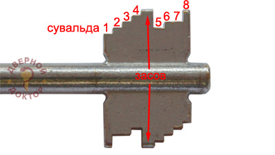
The second beard is similar in structure to the first, with the only difference being that the height of the secrets is somewhat different.
From the height of the secret, as you already understood, depends on how high the lever rises when the key is turned. And whether the bolt will advance in this case depends on the correspondence of the height of the secret on the key to a specific passage groove in the code labyrinth of the lever.
According to the heights of the secret of the key, about the correspondence of the code ledges of the lever, most likely we will talk in subsequent materials, where we will talk about how the number of code combinations of a particular lock model is set and what it all depends on.
This material is already overloaded with information, so let's not insert formulas into it.
On one of the key beards there is a guide protrusion or simply a guide. Under it in the keyhole of the castle there is a corresponding drink.
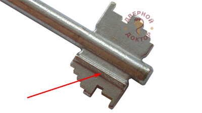
The guide is designed to correctly orient the key inside the lever lock body. The guide helps us put the key in the lock right side, and also prevents it from popping out when exposed.
When we insert the lever key into the well, we insert it all the way - it is the guide that rests against the body.
The guide can look not only like a protrusion, but also like a recess, a groove in the beard of a lever key.
Now let's shove everything that we discussed above into the case and try to assemble something similar to a lever lock.
In our case, the code mechanism of the lever lock contains eight levers. Four are located on one side of the bolt shank, four on the other.
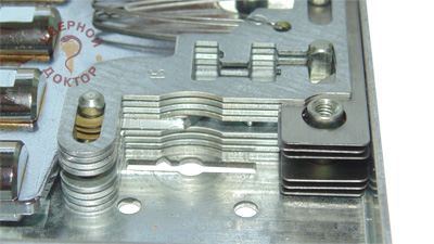
Sometimes the secrecy mechanism of a lever lock is called a “lever package”. Well, because the levers are laid out each strictly in a certain sequence relative to the given code on the key.
In order to reduce friction forces, in order to make the operation of the lever lock more comfortable, and the mechanism more durable, the levers in the package are usually separated by something. In our case, the levers are separated from each other by washers and metal gaskets.
Some locks have plastic gaskets.
Well, in most castles, the levers are separated from each other by bulges, bulges on the surface of the lever itself.
In the lock we are considering, the lever package is divided by the bolt shank.
They also say that the package of the lever lock is 4 + 4. This means that four levers in the mechanism are located before the bolt shank, and four after.
Well, comrades, the time has come to see firsthand the work of the lever lock.
Now, after all that has been said above, you will have practically no questions left about what moves there and how it moves when the key is turned.
Nevertheless, we will give some explanations.
So, the key is inserted into the body of the lever lock until it stops.
Now, under each height of the key is the lever with which it (the height) will interact.
When turning the key, we, overcoming the force of the springs of the working elements, raise the levers until the through groove at all stands exactly opposite the deadbolt shank stand.
Now the bolt is not blocking anything.
But what will move him?
That's right, the drive tooth of the key. We continue to turn the key in the direction of opening the lock and with its drive tooth it begins to move the bolt in the direction of opening.
At the end of the movement of the rack along the code groove, the drive tooth of the key disengages from the gear comb of the deadbolt and stops lifting the levers. Rather, on the contrary, the levers, under the load of their springs, tend to return to their original position and put pressure on the key at the end of each half-turn.
The second half-turn is identical to the first one with the only difference that other key secret cutting heights correspond to other code protrusions and code grooves.
That's the whole principle of the lever lock!
Now let's imagine that they are trying to open our lock with the wrong key, the cutting of which is not correct.
The start of work in this case is exactly the same: when turning the key, we overcome the force of the springs and raise the levers up until the drive tooth touches the gear comb of the deadbolt and begins to move the deadbolt. The cut of the key does not correspond to the lock code; The lever lock and the door remain closed.
We hope that readers scooped a lot useful information about the levers from this opus.
Your comments and near-suvald questions are accepted in the comments below.
The reasons for the breakdown of the door lock can be very different. Sometimes the core of the locking device may fail, the case may crack, the lever locking mechanism may break. However, all troubles can be dealt with.
The latch of the locking device does not close. The reason may be the insufficient diameter of the desired hole. You will need to carefully bore the hole and move the iron plate. The tongue can also be blocked by an overlay at the end of the door leaf or a skew of the door itself. Also, the mechanism can simply loosen up and wear out during prolonged use.
If the door is difficult to open, the cause of the problem is the distortion of the door leaf. It is necessary to adjust not only the position of the door frame, but also the locking device itself.
Poor turning of the key and jamming of the lock is due to the displacement of individual parts of the locking device. It is necessary to disassemble the lock, clean all the elements of the mechanism well, lubricate the parts and install the device in its original place.
Lock jamming. The reason for such a malfunction lies in the larva. It needs repair or replacement.
Repairing a door lock with a broken housing requires the use of a screwdriver. This tool unscrews the mounting bolts. The broken case is replaced with a new one. This method is used in case of breakage of overhead locks. If the case is broken in the mortise lock, then all parts of the mechanism are removed and removed in stages. Using a screwdriver, the screws that secure the case are unscrewed. With the help of tweezers and a cloth, the dirt accumulated in the lock is eliminated, the device is completely cleaned. All bent parts are replaced. The problem can be not only in a broken case, but also in a malfunction of the locking mechanism.
In cylinder devices, which are often installed on the front metal door, there is a secret element - a larva. Its breakdown requires the replacement of the lock core with a new one. To repair the lock, you need to remove the end plate, remove the main bolt, remove the cylinder with a drill or key. The new larva must be identical to the one that is damaged. It is easily inserted into the lock and fixed with fixing screws. Then the end plate is applied on top.
Level lock - enough complex device. If it breaks, a new mechanism must be installed. To carry out repairs, it is necessary to keep the door in open position. A key is pulled out of the keyhole. The deadbolt, handle, armor plate, fixing screws are removed. The old mechanism is pulled out and a new one is installed. To replace the locking device, you need to purchase a mechanism from the same manufacturer.
In rare cases, the cause of a lock malfunction may lie in such an auxiliary element as the counterpart. If the key inserted into the well turns and sets the crossbars in motion, then the counter plate is broken. Then the plate must be bored. To do this, you can call a specialist who will deal with the problem quickly. If the lock or counterpart cannot be repaired on its own, then contacting qualified specialists will solve these problems.
Door locks always break unexpectedly, like any device. This is especially true of the lock in the front door, which requires momentary "help", because the security of the entire home directly depends on it. In a fit of fear for the safety of the house, many turn to specialists, without even assuming that the repair of locks in metal doors can often be done by hand and at home.
The main thing is to study the cause of the malfunction, for which you need to carry out. To do this, stock up the right tools and take the matter as seriously as possible. Opening the lock with your own hands is done with a set of screwdrivers and pliers, and for cleaning and repair you will need tweezers, lubricating oil, a piece of cloth, kerosene and a toothbrush.
The front door lock should be returned to a working condition, being fully aware of the action of the mechanism of the larva, the malfunctions in which entail problems. For metal doors characteristic is the use of cylinder and overhead lever locks.
It is necessary to repair the cylinder lock, following the sequence of actions:
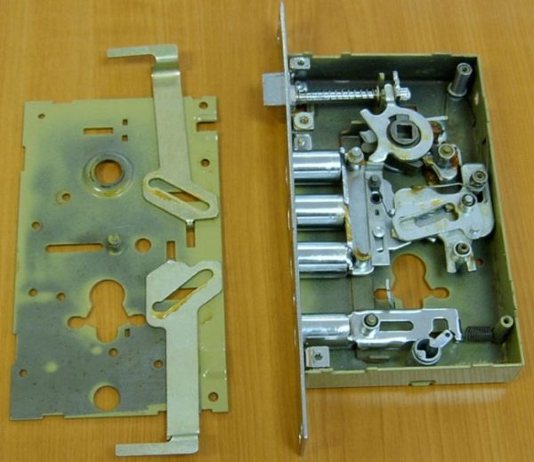
If a lock with a lever mechanism breaks down, then most likely it will be necessary complete replacement lock mechanism: in this case, updating the base, due to the high probability of re-breaking, will only be a temporary solution to the problem.
Actions to return the larvae of the lock mechanism of the front door to working condition will not raise questions even among the “dummies” of carpentry. The most common problem that causes difficulty in using the key is due to clogging of the well.
Repairing the lock cylinder, or replacing it with your own hands, does not involve a complete opening or disassembly of the mechanism - except to unscrew the armor plate.
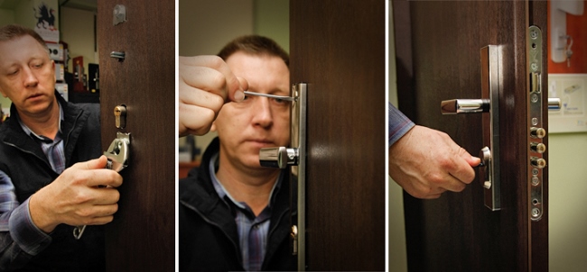
The first step is to dismantle the larva from the structure, using the working part of a Phillips screwdriver. This is done in the following sequence:
If there are violations associated with the lock tongue, for example, periodic short circuits or lack of response to turning the key, then repair of this part is mandatory: ignoring the problem can lead to emergency and irreparable damage.
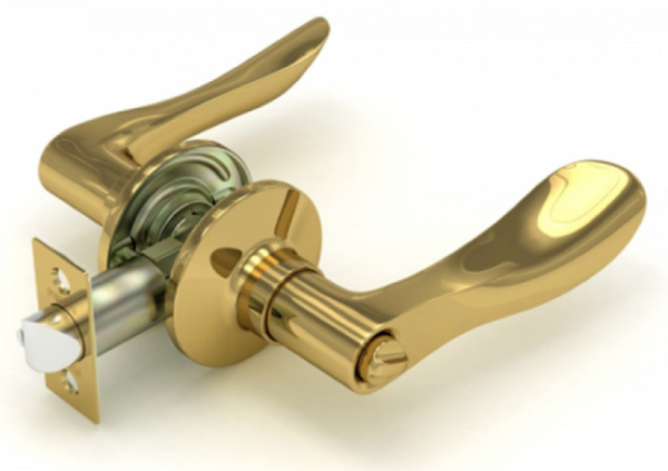
So, it is imperative to check the conformity of the dimensions of the hole to the tongue. The problem of a narrow "hole" is solved by boring and shifting the iron plate. Installing blocking overheads in the end part of the door structure will help fix the loose tongue.
Particular attention is drawn to a worn or loose mechanism: in a critical situation, it is desirable to adjust or update it.
In case of problems with the operation of the crossbar, it is necessary to open the entire mechanism, so it is recommended to consult and help a specialist who knows exactly how to fix a door lock of such a model. However, if the owner is sure that he can do everything with his own hands, then you should:
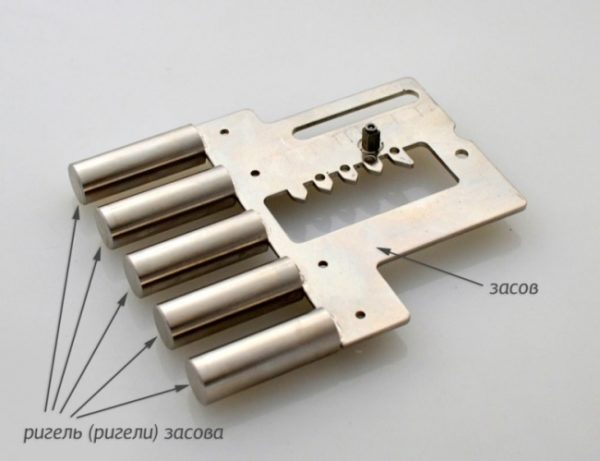
In any case, before you start opening the lock, you should not only soberly assess the abilities, but also ask yourself the question of the feasibility of repair: perhaps the breakdown has become critical, and it would be logical to completely replace the mechanism, rather than its partial and, accordingly, temporary treatment.
Magnetic and electromagnetic locks this is a separate category of locking mechanisms. The first of them serve simply to hold the door and do not require significant effort to open it. They are used exclusively in interior doors and furniture. The whole repair of magnetic locks is to tighten or fix a loose fastener - it all comes down to the locksmith or carpentry part.
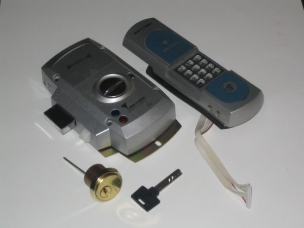
Repair of electromagnetic locks requires some knowledge of electrical engineering, since for their work they are connected to an electrical circuit - if the current is turned off, they open. Their breakdowns, respectively, are divided into two categories - mechanical and electrical. The first can be seen with the naked eye - usually this is a displacement or clogging of the surface of the magnet - all this is easily eliminated with your own hands. If the electrician fails, then the reasons must be sought:
We change the larva in the castle:
In any case, the repair of electromagnetic locks is not only opening the box, but also a complete disassembly of the entire device.
Before, during and after work, the condition of the parts, their serviceability are checked, the location of spare parts is remembered, and the repaired mechanism is checked.
Door structures made of steel or iron require special attention and caution. Sometimes, in the case of a mortise locking system installed in the door, it becomes necessary to use welding, so repairing locks is a matter that requires a lot of attention and effort.