Air flow regulation is part of the process of setting up ventilation and air conditioning systems; it is carried out using special regulating air valves. Regulating air flow in ventilation systems allows you to ensure the required inflow fresh air in each of the serviced premises, and in air conditioning systems - cooling the premises in accordance with their thermal load.
To regulate air flow, air valves, iris valves, systems for maintaining constant air flow (CAV, Constant Air Volume), as well as systems for maintaining variable air flow (VAV, Variable Air Volume) are used. Let's look at these solutions.
In principle, there are only two ways to change the air flow in the air duct - change the fan performance or set the fan to maximum mode and create additional resistance to the movement of air flow in the network.
The first option requires connecting fans through frequency converters or step transformers. In this case, the air flow will change immediately throughout the system. It is impossible to regulate the air supply to one specific room in this way.
The second option is used to regulate air flow in directions - by floor and by room. To do this, various control devices are built into the corresponding air ducts, which will be discussed below.
The most primitive way to regulate air flow is to use air shut-off valves and dampers. Strictly speaking, shut-off valves and dampers are not regulators and should not be used to regulate air flow. However, formally they provide regulation at the “0-1” level: either the duct is open and the air moves, or the duct is closed and the air flow is zero.
The difference between air valves and dampers lies in their design. The valve is usually a body with a butterfly valve inside. If the damper is turned across the axis of the air duct, it is blocked; if along the axis of the air duct, it is open. At the gate, the damper moves progressively, like a wardrobe door. By blocking the cross-section of the air duct, it reduces air flow to zero, and by opening the cross-section, it ensures air flow.
In valves and dampers, it is possible to install the damper in intermediate positions, which formally allows you to change the air flow. However, this method is the most ineffective, difficult to control and the most noisy. Indeed, it is almost impossible to catch the desired position of the damper when scrolling it, and since the design of the dampers does not provide for the function of regulating air flow, in intermediate positions the dampers and dampers make quite a lot of noise.
Iris valves are one of the most common solutions for regulating indoor air flow. They are round valves with petals located along the outer diameter. When adjusted, the petals move towards the valve axis, blocking part of the cross section. This creates a well-streamlined surface from an aerodynamic point of view, which helps reduce noise levels in the process of regulating air flow.
Iris valves are equipped with a scale with marks on which you can monitor the degree of overlap of the valve's live section. Next, the pressure drop across the valve is measured using a differential pressure gauge. The actual air flow through the valve is determined by the pressure drop.
The next stage in the development of technologies for regulating air flow is the emergence of constant flow regulators. The reason for their appearance is simple. Natural changes in the ventilation network, clogged filter, clogged external grille, fan replacement and other factors lead to a change in air pressure in front of the valve. But the valve was set to a certain standard pressure drop. How will it work in the new conditions?
If the pressure in front of the valve has decreased, the old valve settings will “transmit” the network, and the air flow into the room will decrease. If the pressure in front of the valve has increased, the old valve settings will “underpressure” the network, and the air flow into the room will increase.
However, the main task of the control system is precisely to maintain the design air flow in all rooms throughout the entire life cycle climate system. This is where solutions for maintaining constant air flow come to the fore.
The principle of their operation is to automatically change the flow area of the valve depending on external conditions. For this purpose, the valves are equipped with a special membrane, which deforms depending on the pressure at the valve inlet and closes the cross-section when the pressure increases or releases the cross-section when the pressure decreases.
Other constant flow valves use a spring instead of a diaphragm. Increasing pressure in front of the valve compresses the spring. The compressed spring acts on the flow area control mechanism, and the flow area decreases. At the same time, the valve resistance increases, neutralizing the increased pressure upstream of the valve. If the pressure in front of the valve decreases (for example, due to a clogged filter), the spring expands and the flow area control mechanism increases the flow hole.
The considered constant air flow controllers operate on the basis of natural physical principles without the participation of electronics. There are also electronic systems maintaining constant air flow. They measure the actual pressure drop or air velocity and change the valve opening area accordingly.
Systems with variable flow air allow you to change the flow of supplied air depending on the actual state of affairs in the room, for example, depending on the number of people, concentration carbon dioxide, air temperature and other parameters.
Regulators of this type are valves with an electric drive, the operation of which is determined by a controller that receives information from sensors located in the room. Regulation of air flow in ventilation and air conditioning systems is carried out using various sensors.
For ventilation, it is important to provide the required amount of fresh air in the room. In this case, carbon dioxide concentration sensors are used. The task of the air conditioning system is to maintain the set temperature in the room, therefore, temperature sensors are used.
Both systems can also use motion sensors or sensors to determine the number of people in the room. But the meaning of their installation should be discussed separately.
Of course, the more people in the room, the more fresh air should be supplied to it. But still, the primary task of the ventilation system is not to ensure air flow “for people,” but to create a comfortable environment, which in turn is determined by the concentration of carbon dioxide. With a high concentration of carbon dioxide, ventilation should operate in a more powerful mode, even if there is only one person in the room. Likewise, the main indicator of the operation of the air conditioning system is the air temperature, not the number of people.
However, presence sensors make it possible to determine whether a given room needs to be serviced at the moment. In addition, the automation system can “understand” that “it’s late at night”, and it’s unlikely that anyone will work in the office in question, which means there’s no point in wasting resources on air-conditioning it. Thus, in systems with variable air flow, different sensors can perform different functions - to form a regulatory effect and to understand the need for the operation of the system as such.
The most advanced systems with variable air flow allow the generation of a signal to control the fan based on several regulators. For example, during one period of time, almost all regulators are open, the fan operates in high performance mode. At another point in time, some of the regulators reduced the air flow. The fan can operate in a more economical mode. At the third point in time, people changed their location, moving from one room to another. The regulators worked out the situation, but the total air flow remained almost unchanged, therefore, the fan will continue to operate in the same economical mode. Finally, it is possible that almost all regulators are closed. In this case, the fan reduces the speed to a minimum or turns off.
This approach allows you to avoid constant manual reconfiguration of the ventilation system, significantly increase its energy efficiency, increase the service life of the equipment, accumulate statistics on the climatic conditions of the building and its changes throughout the year and during the day, depending on various factors - the number of people, outside temperature, weather conditions .
Yuri Khomutsky, technical editor of Climate World magazine>
Variable air flow regulators KPRK for air ducts round section are designed to maintain a given air flow rate in ventilation systems with variable air flow (VAV) or constant air flow (CAV). In VAV mode, the air flow setpoint can be changed using a signal from an external sensor, controller or from a dispatch system; in CAV mode, the controllers maintain the specified air flow
The main components of flow regulators are an air valve, a special pressure receiver (probe) for measuring air flow and an electric drive with a built-in controller and pressure sensor. The difference between the total and static pressure at the measuring probe depends on the air flow through the regulator. The current pressure difference is measured by a pressure sensor built into the electric drive. An electric drive, controlled by a built-in controller, opens or closes the air valve, maintaining the air flow through the regulator at a given level.
KPRK regulators can operate in several modes depending on the connection diagram and settings. Air flow settings in m3/h are set during programming at the factory. If necessary, the settings can be changed using a smartphone (with NFC support), a programmer, a computer or a dispatch system via the MP-bus, Modbus, LonWorks or KNX protocol.
The regulators are available in twelve versions:
For coordinated operation of several variable air flow regulators KPRK and ventilation unit It is recommended to use Optimizer - a controller that allows you to change the fan speed depending on the current need. You can connect up to eight KPRK regulators to the Optimizer, and also combine, if necessary, several Optimizers in the “Master-Slave” mode. Variable air flow regulators remain operational and can be operated regardless of their spatial orientation, except when the measuring probe fittings are directed downwards. The direction of air flow must correspond to the arrow on the product body. Regulators are made of galvanized steel. Models KPRK-I and KPRK-SH are made in a heat/sound-insulated housing with an insulation thickness of 50 mm; KPRK-SH are additionally equipped with a 650 mm long silencer on the air outlet side. The housing pipes are equipped with rubber seals, which ensures a tight connection with the air ducts.
Imagine that you want to install a ventilation system in your apartment. Calculations show that to heat the supply air in the cold season, a heater with a power of 4.5 kW will be required (it will allow heating the air from -26°C to +18°C with a ventilation capacity of 300 m³/h). Electricity is supplied to the apartment through a 32A automatic machine, so it is easy to calculate that the heater power is about 65% of the total power allocated to the apartment. This means that such a ventilation system will not only significantly increase the amount of energy bills, but also overload the electrical grid. Obviously, it is not possible to install a heater of such power and its power will have to be reduced. But how can this be done without reducing the level of comfort of the apartment's inhabitants?
Ventilation unit with recuperator.
It requires a network to work.
supply and exhaust air ducts.
The first thing that usually comes to mind in such cases is the use of a ventilation system with a recuperator. However, such systems are well suited for large cottages, in apartments there is simply not enough space for them: in addition to the supply air network, an exhaust network must be connected to the recuperator, doubling the total length of the air ducts. Another disadvantage of recovery systems is that in order to organize air support for “dirty” rooms, a significant part of the exhaust flow must be directed to the exhaust ducts of the bathroom and kitchen. And the imbalance of the supply and exhaust flows leads to a significant decrease in the efficiency of recovery (it is impossible to refuse air pressure in “dirty” rooms, since in this case unpleasant odors will begin to circulate throughout the apartment). In addition, the cost of a recuperative ventilation system can easily exceed twice the cost of a conventional supply system. Is there another, inexpensive solution to our problem? Yes, this is a supply VAV system.
Variable air flow system or VAV(Variable Air Volume) system allows you to regulate the air supply in each room independently of each other. With such a system, you can turn off the ventilation in any room in the same way as you are used to turning off the lights. Indeed, we don’t leave the lights on where there is no one - this would be an unreasonable waste of electricity and money. Why let a ventilation system with a powerful heater waste energy? However, this is exactly how traditional ventilation systems work: they supply heated air to all rooms where people could be, regardless of whether they are actually there. If we controlled light just like traditional ventilation- it would burn in the whole apartment at once, even at night! Despite obvious advantage VAV systems, in Russia, unlike Western Europe, they have not yet become widespread, partly because their creation requires complex automation, which significantly increases the cost of the entire system. However, the rapid reduction in the cost of electronic components, which is occurring in Lately, made it possible to develop inexpensive ready-made solutions for building VAV systems. But before we move on to describing examples of systems with variable air flow, let's figure out how they work.
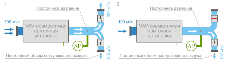
The illustration shows a VAV system with a maximum capacity of 300 m³/h, serving two areas: living room and bedroom. In the first picture, air is supplied to both zones: 200 m³/h in the living room and 100 m³/h in the bedroom. Let us assume that in winter the power of the heater will not be enough to heat such an air flow to comfortable temperature. If we used a conventional ventilation system, we would have to reduce the overall performance, but then both rooms would become stuffy. However, we have a VAV system installed, so we can only supply air to the living room during the day and only supply air to the bedroom at night (as in the second picture). For this purpose, the valves that regulate the volume of air supplied to the premises are equipped with electric drives, which allow the valve dampers to be opened and closed using conventional switches. Thus, by pressing the switch, the user, before going to bed, turns off the ventilation in the living room, where there is no one at night. At this moment, the differential pressure sensor, which measures the air pressure at the outlet of the air handling unit, records an increase in the measured parameter (when the valve is closed, the resistance of the air supply network increases, leading to an increase in air pressure in the air duct). This information is transmitted to the air handling unit, which automatically reduces the fan performance just enough so that the pressure at the measuring point remains unchanged. If the pressure in the air duct remains constant, then the air flow through the valve in the bedroom will not change, and will still be 100 m³/h. The overall performance of the system will decrease and will also be equal to 100 m³/h, that is, the energy consumed by the ventilation system at night will decrease by 3 times without compromising people's comfort! If you turn on the air supply alternately: during the day in the living room, and at night in the bedroom, then the maximum power of the heater can be reduced by a third, and the average energy consumption by half. The most interesting thing is that the cost of such a VAV system exceeds the cost of a conventional ventilation system by only 10-15%, that is, this overpayment will be quickly compensated by reducing the amount of electricity bills.
A short video presentation will help you better understand the operating principle of the VAV system:
Now, having understood the operating principle of a VAV system, let’s see how one can assemble such a system based on equipment available on the market. We will take as a basis the Russian VAV-compatible air handling units Breezart, which allow you to create VAV systems serving from 2 to 20 zones with centralized control from a remote control, by a timer or a CO 2 sensor.
This VAV system is assembled on the basis of a Breezart 550 Lux air handling unit with a capacity of 550 m³/h, which is sufficient to serve an apartment or small cottage (taking into account that a system with variable air flow may have lower productivity compared to a traditional ventilation system). This model, like all other Breezart ventilation units, can be used to create a VAV system. Additionally we will need a set VAV-DP, which includes a JL201DPR sensor that measures the pressure in the duct near the branch point.

VAV system for two zones with 2-position control
The ventilation system is divided into 2 zones, and the zones can consist of either one room (zone 1) or several (zone 2). This allows the use of such 2-zone systems not only in apartments, but also in cottages or offices. The valves in each zone are controlled independently of each other using conventional switches. Most often, this configuration is used to switch night (air supply only to zone 1) and day (air supply only to zone 2) modes with the ability to supply air to all rooms if, for example, you have guests.
Compared to a conventional system (without VAV control), the increase in cost of basic equipment is approx. 15% , and if we take into account the total cost of all elements of the system together with installation work, then the increase in cost will be almost unnoticeable. But even such a simple VAV system allows save about 50% electricity!
In the example given, we used only two controlled zones, but there can be any number of them: the air supply unit simply maintains the specified pressure in the air duct, regardless of the configuration of the air network and the number of controlled VAV valves. This allows, if there is a lack of funds, to first install a simple VAV system in two zones, subsequently increasing their number.
So far we have looked at 2-position control systems, in which the VAV valve is either 100% open or completely closed. However, in practice more often they are used convenient systems with proportional control, allowing you to smoothly regulate the volume of supplied air. We will now consider an example of such a system.

VAV system for three zones with proportional control
This system uses a more productive Breezart 1000 Lux PU at 1000 m³/h, which is used in offices and cottages. The system consists of 3 zones with proportional control. CB-02 modules are used to control proportional valve actuators. Instead of switches, JLC-100 regulators (outwardly similar to dimmers) are used here. This system allows the user to smoothly adjust the air supply in each zone in the range from 0 to 100%.
Composition of the basic equipment of the VAV system (air handling unit and automation)
Note that one VAV system can simultaneously use zones with 2-position and proportional control. In addition, control can be carried out from motion sensors - this will allow air to be supplied to the room only when there is someone in it.
The disadvantage of all the considered VAV system options is that the user has to manually adjust the air supply in each zone. If there are many such zones, then it is better to create a system with centralized control.
Centralized control of the VAV system allows you to activate pre-programmed scenarios, changing the air supply simultaneously in all zones. For example:

VAV system for three zones with centralized control
For centralized control of valve actuators, JL201 modules are used, which are combined into a single system controlled via the ModBus bus. Programming of scenarios and control of all modules is carried out from the standard remote control of the ventilation unit. The JL201 module can be connected to a carbon dioxide concentration sensor or a JLC-100 controller for local (manual) control of actuators.
Composition of the basic equipment of the VAV system (air handling unit and automation)
The video describes how to control a VAV system with centralized control for 7 zones from the remote control of the Breezart 550 Lux air handling unit:
With these three examples we have shown general principles construction and briefly described the capabilities of modern VAV systems; more detailed information about these systems can be found on the Breezart website.
|
|
|
|
Variable Air Volume (VAV) systems are an energy-efficient ventilation system that allows you to save energy without compromising comfort levels. The system makes it possible to independently regulate ventilation parameters for each individual room, and also saves capital and operating costs.
The modern base of equipment and automation makes it possible to create such systems at prices almost no higher than the prices of conventional ventilation systems, while allowing for efficient use of resources. All these are the reasons for the growing popularity of the VAV system.
Let's look at what a VAV system is, how it works, and what advantages it provides, using the example of the ventilation system of a cottage with an area of 250 sq.m. ().
Variable Air Volume (VAV) systems have been widely used for several decades in America and Western Europe, on Russian market they arrived just recently. Users Western countries highly appreciated the advantage of independent regulation of ventilation parameters for each individual room, as well as the possibility of saving capital and operating costs.
“Variable Air Volume” ventilation systems operate in the mode of changing the amount of air supplied. Changes in the heat load of the premises are compensated by changing the volumes of supply and exhaust air with him constant temperature, coming from the central air supply unit.
The VAV ventilation system responds to changes in the heat load of individual rooms or zones of the building and changes the actual amount of air supplied to the room or zone.
Due to this, ventilation operates at general meaning air flow less than necessary for the total maximum heat load of all individual rooms.
This ensures reduced energy consumption while maintaining desired indoor air quality. The reduction in energy costs can range from 25-50% compared to ventilation systems with constant air flow.
Let's look at efficiency using ventilation as an example. country house
250 m², with three bedrooms
With a traditional ventilation system, for a living space of this area, an air flow of about 1000 m³/h is required, and in winter it will take about 15 kWh to heat the supply air to a comfortable temperature. In this case, a significant part of the energy will be wasted, because the people for whom the ventilation is working cannot be in the entire cottage at once: they spend the night in the bedrooms and the day in other rooms. However, it is impossible to selectively reduce the performance of a traditional ventilation system in several rooms, since the balancing of the air valves, with which you can regulate the air supply to the rooms, is carried out at the commissioning stage, and during operation the flow rate ratio cannot be changed. The user can only reduce the overall air flow, but then the rooms where people are located will become stuffy.
If you connect electric drives to the air valves, which will allow you to remotely control the position of the valve damper and thereby regulate the air flow through it, then you can turn the ventilation on and off separately in each room using conventional switches. The problem is that managing such a system is very difficult, because simultaneously with closing some of the valves, it will be necessary to reduce the performance of the ventilation system by a strictly defined amount so that the air flow in the remaining rooms remains unchanged and as a result, improvement will turn into a headache.
Using a VAV system will allow all these adjustments to be made automatically. And so we install the simplest VAV system, which allows you to separately turn on and off the air supply to the bedrooms and other rooms. In night mode, air is supplied only to the bedrooms, therefore the air flow is about 375 m³/h (based on 125 m³/h for each bedroom, area 20 m²), and energy consumption is about 5 kWh, that is, 3 times less than in the first option.
Having received the possibility of separate control, in different rooms you can supplement the system with the latest climate control automation, so the use of valves with proportional electric drives will make control smooth and even more convenient; and if we connect the air supply on/off based on a signal from the presence sensor, we get an analogue of the “Smart Eye” system used in household split systems, but at a completely new level. For further atomization, sensors for temperature, humidity, CO2 concentration, etc. can be built into the system, which ultimately will not only save energy, but will also significantly increase the level of comfort.
If all the automation units that control the electric drives of the air valves are connected by a single control bus, then it will be possible to centralize scenario control of the entire system. Thus, you can create and set individual operating modes for different rooms, in different life situations, So:
at night- air is supplied only to the bedrooms, and in other rooms the valves are open at a minimum level; during the day- air is supplied to rooms, kitchens, and other rooms, except bedrooms. In bedrooms, valves are closed or open at a minimum level.
whole family to gather- we increase the air flow in the living room; no one in the house- cyclic ventilation is set up, which will prevent odors and dampness from occurring, but will save resources.
To independently control not only the volume, but also the temperature of the supply air, additional heaters (low-power air heaters) controlled by individual power regulators can be installed in each room. This will allow air to be supplied from the ventilation unit at the minimum permissible temperature (+18°C), individually heating it to the required level in each room. This technical solution will further reduce energy consumption and bring us closer to the system " Smart House».
The scheme of operation of such a system is rather a question for a specialized specialist, so here we will present only one, the simplest scheme (working and erroneous options) with an explanation of how it works. But besides simple systems, there are also more complex options that allow you to create any VAV systems - from household budget systems with two valves to multi-function ventilation systems administrative buildings with floor-by-floor air flow control.
Call, specialists from the UWC Engineering company will advise and help you choose best option, will design and install a VAV system that is ideal for you.
The easiest way to answer this question is with an example. Let's consider a typical configuration of a system with variable air flow and errors that can be made during its design. The illustration shows an example of the correct configuration of the air supply network of a VAV system:
1. Correct diagram of a VAV system with variable air flow

At the top there is a controlled valve that serves three rooms (three bedrooms in our example) => These rooms have manually operated throttle valves for balancing during commissioning. The resistance of these valves will not change* during operation, therefore they do not affect the accuracy of maintaining air flow.
A manually controlled valve is connected to the main air duct, which has a constant air flow P=const. Such a valve may be needed to ensure normal operation of the ventilation unit when all other valves are closed. => The air duct with this valve is discharged into the room with a constant air supply.
The scheme is simple, working and effective.
Now let's look at the mistakes that can be made when designing the air supply network of a VAV system:
2. Diagram of a VAV system with an error 
Incorrect duct branches are highlighted in red. Valves #2 and 3 are connected to an air duct running from the branch point to VAV valve #1. When you change the position of the valve flap No. 1, the pressure in the air duct near valves No. 2 and 3 will change, so the air flow through them will not be constant. Controlled valve No. 4 cannot be connected to the main air duct, since changes in the air flow through it will cause the pressure P2 (at the branch point) to not be constant. And valve No. 5 cannot be connected as shown in the diagram, for the same reason as valves No. 2 and 3.
*Of course, you can set up controlled airflow for each bedroom, but in this case it will be more complex circuit, which we do not consider within the scope of this article.
The main purposes of this system are: reducing operating costs and compensating for filter contamination.
Using a differential pressure sensor, which is installed on the controller board, the automation recognizes the pressure in the channel and automatically equalizes it by increasing or decreasing the fan speed. Supply and exhaust fan at the same time they work synchronously.
When operating a ventilation system, the filters inevitably become dirty, the resistance of the ventilation network increases and the volume of air supplied to the premises decreases. The VAV system will allow you to maintain a constant air flow throughout the entire life of the filters.
The VAV system can significantly reduce operating costs, this is especially noticeable in supply ventilation systems, which have high energy consumption. Savings are achieved by completely or partially turning off the ventilation of individual rooms.

At calculation of the ventilation system are guided by various standards air consumption per person.
Typically, in an apartment or house, all rooms are ventilated simultaneously; the air flow for each room is calculated based on the area and purpose.
What to do if there is no one in the room at the moment?
You can install valves and close them, but then the entire volume of air will be distributed throughout the remaining rooms, but this will lead to increased noise and waste of air, the precious kilowatts were spent heating it.
You can reduce the power of the ventilation unit, but this will also reduce the volume of air supplied to all rooms, and where users are present there will be “not enough air”.
The best decision, is to supply air only to those rooms where there are users. And the power of the ventilation unit must be regulated itself, according to the required air flow.
This is exactly what a VAV ventilation system allows you to do.
VAV systems pay for themselves quite quickly, especially on air supply units, but most importantly, they can significantly reduce operating costs.

 The volume of air supplied to the room is controlled by electric valves.
An important condition for constructing a VAV system is the organization of the minimum supplied air volume. The reason for this condition lies in the inability to control air flow below a certain minimum level.
To do this, you will need a household switch and a valve with a return spring. Switching on will lead to the full opening of the valve, and the room will be ventilated in full. When switched off, the return spring closes the valve.
 Damper switch/switch.
The minimum required volume of air is always supplied to room No. 1; it cannot be turned off; room No. 2 can be turned on and off.

The minimum required volume of air is distributed to all rooms, since the valves are not completely closed and a minimum amount of air passes through them. The entire room can be turned on and off.

This will require a rotary regulator and a proportional valve. This valve can open by adjusting the volume of supplied air in the range from 0 to 100%, the required degree of opening is set by the regulator.
 Circular regulator 0-10V
The minimum required volume of air is always supplied to room No. 1; it cannot be turned off; room No. 2 can be turned on and off. In room No. 2 you can smoothly regulate the volume of supplied air.
Small opening (valve 25% open) Medium opening (valve 65% open)

The minimum required volume of air is distributed to all rooms, since the valves are not completely closed and a minimum amount of air passes through them. The entire room can be turned on and off. In each room you can smoothly regulate the volume of supplied air.

This will require a presence sensor and a valve with a return spring. When registering in the user’s room, the presence sensor opens the valve and the room is ventilated in full. When there is no user, the return spring closes the valve.

Motion Sensor
The minimum required volume of air is always supplied to room No. 1; it cannot be turned off. When the user registers, ventilation of room No. 2 begins

The minimum required volume of air is distributed to all rooms, since the valves are not completely closed and a minimum amount of air passes through them. When a user registers in any of the rooms, ventilation of this room begins.

This requires a CO2 sensor with a 0...10V signal and a proportional valve with 0...10V control.
When the CO2 level in the room is detected, the sensor begins to open the valve in accordance with the recorded CO2 level.
When the CO2 level decreases, the sensor begins to close the valve, and the valve can close either completely or to a position at which the required minimum flow will be maintained.

 Wall or duct CO2 sensor
The main reason why room ventilation is required is if the CO2 level is too high.
In the process of life, a person exhales a significant amount of air with a high level of CO2 and being in an unventilated room, the level of CO2 in the air inevitably increases, this is what determines when they say that there is “little air”.
It is best to supply air into the room when the CO2 level exceeds 600-800 ppm.
Based on this air quality parameter, you can create the most energy efficient system ventilation.

The minimum required volume of air is distributed to all rooms, since the valves are not completely closed and a minimum amount of air passes through them. When an increase in CO2 content is detected in any room, ventilation of that room begins. The degree of opening and the volume of air supplied depends on the level of excess CO2 content.

To do this, you will need a Smart Home system and any type of valves. Any type of sensors can be connected to the Smart Home system.
Air distribution can be controlled either through sensors using a control program, or by the user from a central control panel or a phone application.

Smart home panel


