DIY Gauss Gun
Since they have already started to appear in one of the articles with Gauss guns, or in another way Gauss Gun which are made with your own hands, in this article I publish another design and video footage of a Gauss gun.
This Gauss gun powered by battery in 12 Volt. You can see it in the picture.
This article can also be used as an instruction, as it describes in detail the assembly of the gun.
Gun characteristics:
Weight:2.5 kg
Projectile speed: approximately 9 m/s
Projectile weight: 29 g
Projectile kinetic energy: approximately 1.17 J.
Charging time of capacitors from the battery through the converter: 2 sec
Charging time of capacitors from the network through the converter: about 30 seconds
Dimensions: 200x70x170 mm
This electromagnetic accelerator is capable of firing any metal projectiles that are magnetic. A Gauss gun consists of a coil and capacitors. When electric current flows through the coil, an electromagnetic field is formed, which in turn accelerates the metal projectile. The purpose is very different - mainly to scare your classmates. In this article I will tell you how to make such a Gauss gun for yourself.
Block diagram of Gauss Cannon

I would like to clarify a point. On the block diagram, the capacitor is 450 Volts. And 500 Volts comes out of the multiplier. Absurd. Isn’t it? Well, the author did not take this into account a little. We set the capacitor to at least 500 Volts.
And now the multiplier circuit itself:

In the scheme field is used transistor IRF 3205.With this transistor charging speed a 1000 uF capacitor for a voltage of 500 volts will be approximately equal to 2 seconds(with 4 amp/hour battery). You can use the IRL3705 transistor, but the charging speed will be approximately 10 seconds. Here is a video of the converter working:
The video multiplier contains an IRL3705 transistor, so the capacitors take a long time to charge. Later I replaced the IRL3705 with the IRF 3205, the charging speed became equal to 2 seconds.
Resistor R7 regulated output voltage from 50 to 900 volts; LED 1 indicates when the capacitors have been charged to the required voltage. If the multiplier transformer is noisy, try reducing the capacitance of capacitor C1, inductor L1 is not necessary, the capacitance of capacitor C2 can be reduced to 1000 µF, diodes D1 and D2 can be replaced with other diodes with similar characteristics. IMPORTANT! Switch S1 is closed only after voltage is applied to the power terminals. Otherwise, if voltage is applied to the terminals and switch S1 is closed, the transistor may fail due to a sharp voltage surge!
The circuit itself works simply: the UC3845 microcircuit produces rectangular pulses, which are fed to the gate of a powerful field-effect transistor, where they are amplified in amplitude and fed to the primary winding of a pulse transformer. Next, the pulses, pumped up by a pulse transformer to an amplitude of 500-600 volts, are rectified by diode D2 and the rectified voltage charges the capacitors. The transformer is taken from a computer power supply. The diagram shows dots near the transformer. These points indicate the beginning of the winding. The method of winding the transformer is as follows:
1 . We cook a transformer taken from an unnecessary computer power supply (the largest transformer) in boiling water for 5-10 minutes, then carefully disassemble the W-shaped ferrite core and unwind the entire transformer.
2
. First, we wind HALF of the secondary winding with a wire with a diameter of 0.5-0.7 mm. You need to wind it from the leg at the point indicated in the diagram.
Having wound 27 turns, we remove the wire without biting it off, insulate 27 turns with paper or cardboard and remember in which direction the wire was wound. THIS IS IMPORTANT!!! If the primary winding is wound in the other direction, then nothing will work, since the currents will be subtracted!!!

3 . Next we wind the primary winding. We also wind it from the beginning indicated in the diagram. We wind it in the same direction in which the first part of the primary winding was wound. The primary winding consists of 6 wires soldered together and wound with 4 turns. We wind all 6 wires parallel to each other, laying them out evenly in 4 turns in two layers. Between the layers we lay a layer of insulating paper.
4 . Next, we wind the secondary winding (another 27 turns). We head in the same direction as before. And now the transformer is ready! All that remains is to assemble the circuit itself. If the circuit is made correctly, the circuit works immediately without any adjustments.
Converter parts:

The converter requires powerful source energy as a 4 ampere/hour battery. The more powerful the battery, the faster the capacitors charge.
Here is the converter itself:

Converter printed circuit board - bottom view:

This board is quite large and after a little work, I drew a smaller board in Sprint-layout:

For those who are not able to make a converter, there is a version of the Gauss gun from a ~220 volt network. Here is the circuit of the multiplier from the network:

You can take any diodes that maintain a voltage above 600 volts; the capacitance of the capacitor is selected experimentally from 0.5 to 3.3 μF.
If the circuit is created correctly, it will work immediately without any settings.
My coil is 8 ohm. It is wound with varnished copper wire with a diameter of 0.7 mm. total length wires are about 90 meters.

Now that everything is done, all that remains is to assemble the gun itself. The total cost of the gun is about 1000 rubles. The cost was calculated as follows:
For those who want to make the same gun as mine, here are step-by-step instructions:
1) Cut out a piece of plywood measuring 200x70x5 mm.
2) We make a special mount for the handle. You can make a handle from a toy pistol, but I have the handle of an insulin injection pistol. A button with two positions (three outputs) is installed inside the handle.
3) Install the handle.
4) We make fastenings on plywood for the converter.

5) Install the converter on the plywood.
6) We make a protective shield on the converter so that the projectile does not damage the converter.

7) Install the coil and solder all the wires as in the block diagram.

8) We make the body from fiberboard

9) We install all the switches in place, secure the battery with large ties. That's all! The gun is ready! This gun fires the following projectiles:

The diameter of the projectile is 10 mm, and the length is 50 mm. Weight 29 grams.
Raised body gun:

And finally, a few videos
Here is a video of a Gauss gun in action. Shot into a corrugated cardboard box
Shot at 0.8mm thick tile:
Nov 19, 2014
Firstly, the editors of Science Debate congratulate all the artillerymen and rocketeers! After all, today is November 19—Rocket Forces and Artillery Day. 72 years ago, on November 19, 1942, the Red Army’s counteroffensive during the Battle of Stalingrad began with powerful artillery preparation.
That is why today we have prepared for you a publication dedicated to cannons, but not ordinary ones, but Gauss cannons!
A man, even when he becomes an adult, remains a boy at heart, but his toys change. Computer games have become a real salvation for respectable men who did not finish playing “war games” in childhood and now have the opportunity to make up for lost time.
Computer action films often feature futuristic weapons that you won’t find in real life- the famous Gauss cannon, which can be planted by some crazy professor or can be accidentally found in a secret chronicle.
It turns out that it is possible, and it is not as difficult to do as it might seem at first glance. Let's quickly find out what a Gauss gun is in the classical sense. A Gauss gun is a weapon that uses a method of electromagnetic mass acceleration.
The design of this formidable weapon is based on a solenoid - a cylindrical winding of wires, where the length of the wire is many times greater than the diameter of the winding. When will it be served? electricity, a strong magnetic field will arise in the cavity of the coil (solenoid). It will pull the projectile inside the solenoid.
If at the moment when the projectile reaches the center, the voltage is removed, then the magnetic field will not prevent the body from moving by inertia, and it will fly out of the coil.
In order to create a Gauss gun with our own hands, we first need an inductor. Carefully wind the enameled wire onto the bobbin, without sharp bends, so as not to damage the insulation in any way.
After wrapping, fill the first layer with superglue, wait until it dries, and proceed to the next layer. In the same way you need to wind 10-12 layers. We put the finished coil on the future barrel of the weapon. A plug should be placed on one of its edges.

In order to get a strong electrical impulse, a bank of capacitors is perfect. They are able to release the accumulated energy for a short time until the bullet reaches the middle of the coil.
To charge the capacitors you will need Charger. A suitable device is found in photographic cameras; it is used to produce a flash. Of course, we are not talking about an expensive model that we will dissect, but disposable Kodaks will do.
In addition, apart from the charger and capacitor, they do not contain any other electrical elements. When disassembling the camera, be careful not to receive an electric shock. Feel free to remove the battery clips from the charging device and unsolder the capacitor.
Thus, you need to prepare approximately 4-5 boards (more is possible if desire and capabilities allow). The question of choosing a capacitor forces you to make a choice between the power of the shot and the time it takes to charge. A larger capacitor capacity also requires a longer period of time, reducing the rate of fire, so you will have to find a compromise.

LED elements installed on the charging circuits signal with light that the required charging level has been reached. Of course, you can connect additional charging circuits, but do not overdo it, so as not to accidentally burn the transistors on the boards. In order to discharge the battery, it is best to install a relay for safety reasons.
We connect the control circuit to the battery through the shutter button, and the controlled circuit to the circuit between the coil and the capacitors. In order to fire a shot, you need to supply power to the system and, after the light signal, charge the weapon. Turn off the power, aim and shoot!
If the process captivates you, but the resulting power is not enough, then you can start creating a multi-stage Gauss gun, because that’s exactly what it should be like.
Modern artillery guns are an alloy latest technologies, pinpoint accuracy of destruction and increased power of ammunition. And yet, despite colossal progress, guns of the 21st century shoot the same way as their great-grandmothers - using the energy of powder gases.
Electricity was able to shake the monopoly of gunpowder. The idea of creating an electromagnetic gun arose almost simultaneously in Russia and France at the height of the First World War. It is based on the works of the German researcher Johann Carl Friedrich Gauss, who developed the theory of electromagnetism, embodied in an unusual device - an electromagnetic gun.


 Operating principle of a Gauss gun
The advantages of the Gauss electromagnetic gun compared to other types of weapons are the ability to flexibly vary initial speed and the energy of the projectile, as well as the noiselessness of the shot. There is also a drawback - low efficiency, amounting to no more than 27%, and the associated large energy costs. Therefore, in our time, the Gauss gun has prospects rather as an amateur installation. However, the idea can get a second life if new compact and ultra-powerful current sources are invented.

 Operating principle of a railgun


Similar developments are still underway in Russia. A team from one of the branches of the United Institute recently demonstrated its vision of a railgun high temperatures RAS. An electromagnetic accelerator was developed to accelerate the charge. Here, a bullet weighing several grams was accelerated to a speed of about 6.3 km/sec.

Information is provided for educational purposes only!
The site administrator is not responsible for possible consequences use of the information provided.
CHARGED CAPACITORS DEADLY DANGEROUS!
Electromagnetic gun (Gauss gun, English. coilgun) in her classic version is a device that uses the property of ferromagnetic materials to be drawn into a region of a stronger magnetic field to accelerate a ferromagnetic “projectile”.
My gauss gun:
view from above: 
side view: 
1 - connector for connecting a remote release
2 - “battery charge/work” switch
3 - connector for connecting to a computer sound card
4 - capacitor charge/shot switch
5 - emergency capacitor discharge button
6 - "Battery charge" indicator
7 - "Work" indicator
8 - "Charge of capacitor" indicator
9 - "Shot" indicator
Diagram of the power part of the Gauss gun:

1 - trunk
2 - protective diode
3 - coil
4 - IR LEDs
5 - IR phototransistors
The main design elements of my electromagnetic gun:
battery
-
I use two lithium ion batteries SANYO UR18650A 18650 format from a laptop with a capacity of 2150 mAh, connected in series:
...
The maximum discharge voltage of these batteries is 3.0 V.
voltage converter for powering control circuits -
The voltage from the batteries is supplied to a step-up voltage converter on the 34063 chip, which increases the voltage to 14 V. Then the voltage is supplied to the converter to charge the capacitor, and stabilized to 5 V by the 7805 chip to power the control circuit.
voltage converter for charging the capacitor
-
boost converter based on 7555 timer and MOSFET-transistor ;
- This N-channel MOSFET- transistor in housing TO-247 with the maximum permissible drain-source voltage VDS= 500 volts, maximum pulsed drain current I D= 56 amperes and typical open-state drain-to-source resistance RDS(on)= 0.33 ohm. 
The inductance of the converter choke affects its operation:
too low inductance determines low speed capacitor charge;
too high an inductance can lead to core saturation.
As a pulse generator ( oscillator circuit) for converter ( boost converter) you can use a microcontroller (for example, the popular Arduino), which will allow implementing pulse width modulation (PWM, PWM) to control the duty cycle of pulses.
capacitor (coil cap(acitor)) -
electrolytic capacitor for a voltage of several hundred volts.
Previously, I used a K50-17 capacitor from a Soviet external flash with a capacity of 800 μF for a voltage of 300 V: 
The disadvantages of this capacitor are, in my opinion, the low operating voltage, increased leakage current (leads to more long charging) and possibly overestimated capacity.
Therefore, I switched to using imported modern capacitors: 
SAMWHA for voltage 450 V with a capacity of 220 μF series HC. HC- This standard series capacitors SAMWHA, there are other series: HE- operating in a wider temperature range, H.J.- with increased lifetime;
PEC for a voltage of 400 V with a capacity of 150 μF.
I also tested a third capacitor for a voltage of 400 V with a capacity of 680 μF, purchased from an online store dx.com -
In the end I settled on using a capacitor PEC for a voltage of 400 V with a capacity of 150 μF.
For a capacitor, its equivalent series resistance ( ESR).
switch -
power switch S.A. designed for switching a charged capacitor C per reel L:
either thyristors or IGBT-transistors:
thyristor
-
I use power thyristor ТЧ125-9-364 with cathode control
appearance
dimensions  - high-speed pin thyristor: “125” means the maximum permissible effective current (125 A); "9" means the class of the thyristor, i.e. repetitive pulse voltage in hundreds of volts (900 V).
Using a thyristor as a key requires selecting the capacitance of the capacitor bank, since a prolonged current pulse will lead to the retraction of a projectile that has passed the center of the coil back - " suck-back effect".
IGBT transistor -
use as a key IGBT-transistor allows not only to close, but also to open the coil circuit. This allows the current (and the coil's magnetic field) to be interrupted after the projectile passes through the center of the coil, otherwise the projectile would be pulled back into the coil and therefore slow down. But opening the coil circuit (a sharp decrease in current in the coil) leads to the appearance of a high voltage pulse on the coil in accordance with the law electromagnetic induction$u_L = (L ((di_L) \over (dt)) )$. To protect the key -IGBT-transistor, additional elements must be used: 
VD TVs- diode ( TVS diode), creating a path for the current in the coil when the key is opened and dampening a sharp voltage surge on the coil
Rdis- discharge resistor ( discharge resistor) - provides attenuation of the current in the coil (absorbs the energy of the magnetic field of the coil)
C rsringing suppression capacitor), preventing the occurrence of overvoltage pulses on the key (can be supplemented with a resistor, forming RC-snubber)
I used IGBT-transistor IRG48BC40F from the popular series IRG4.
coil -
the coil is wound on plastic frame copper wire. The ohmic resistance of the coil is 6.7 ohms. The width of the multilayer winding (in bulk) $b$ is equal to 14 mm, there are about 30 turns in one layer, the maximum radius is about 12 mm, the minimum radius $D$ is about 8 mm (average radius $a$ is about 10 mm, height $c $ - about 4 mm), wire diameter - about 0.25 mm.
A diode is connected in parallel to the coil UF5408 (suppression diode) (peak current 150 A, peak reverse voltage 1000 V), dampening the self-induction voltage pulse when the current in the coil is interrupted.
barrel
-
made from casing ballpoint pen.
projectile -
The parameters of the test projectile are a piece of nail with a diameter of 4 mm (barrel diameter ~ 6 mm) and a length of 2 cm (the volume of the projectile is 0.256 cm 3 and the mass $m$ = 2 grams, if we take the steel density to be 7.8 g/cm 3 ). I calculated the mass by imagining the projectile as a combination of a cone and a cylinder. 
The projectile material must be ferromagnetic.
Also, the projectile material should have as much high magnetic saturation threshold - saturation induction value $B_s$. One of best options is ordinary soft magnetic iron (for example, ordinary non-hardened steel St. 3 - St. 10) with a saturation induction of 1.6 - 1.7 Tesla. Nails are made from low-carbon thermally untreated steel wire (steel grades St. 1 KP, St. 2 KP, St. 3 PS, St. 3 KP).
Steel designation:
Art.- carbon steel of ordinary quality;
0 - 10
- percentage of carbon increased by 10 times. As the carbon content increases, the saturation induction $B_s$ decreases.
And the most effective is the alloy " permendur", but it is too exotic and expensive. This alloy consists of 30-50% cobalt, 1.5-2% vanadium and the rest is iron. Permendur has the highest saturation induction $B_s$ of all known ferromagnets up to 2.43 Tesla.
It is also desirable that the projectile material has as much low conductivity. This is due to the fact that eddy currents arising in an alternating magnetic field in the conducting rod lead to energy losses.
Therefore, as an alternative to nail cutting projectiles, I tested a ferrite rod ( ferrite rod), taken from the inductor from the motherboard: 
Similar coils are also found in computer power supplies: 
Appearance of a ferrite core coil: 
Rod material (probably nickel-zinc ( Ni-Zn) (analogue of domestic brands of ferrite NN/VN) ferrite powder) is dielectric, which eliminates the occurrence of eddy currents. But the disadvantage of ferrite is the low saturation induction $B_s$ ~ 0.3 Tesla.
The length of the rod was 2 cm: 
The density of nickel-zinc ferrites is $\rho$ = 4.0 ... 4.9 g/cm 3 .
Projectile gravity
The calculation of the force acting on a projectile in a Gauss gun is complex task.
Several examples of calculating electromagnetic forces can be given.
The force of attraction of a piece of ferromagnet to a solenoid coil with a ferromagnetic core (for example, a relay armature to a coil) is determined by the expression $F = (((((w I))^2) \mu_0 S) \over (2 ((\delta)^ 2)))$, where $w$ is the number of turns in the coil, $I$ is the current in the coil winding, $S$ is the cross-sectional area of the coil core, $\delta$ is the distance from the coil core to the attracted piece. In this case, we neglect the magnetic resistance of ferromagnets in the magnetic circuit.
The force drawing a ferromagnet into the magnetic field of a coreless coil is given by $F = ((w I) \over 2) ((d\Phi) \over (dx))$.
In this formula, $((d\Phi) \over (dx))$ is the rate of change of the magnetic flux of the coil $\Phi$ when moving a piece of ferromagnet along the axis of the coil (changing the coordinate $x$), this value is quite difficult to calculate. The above formula can be rewritten as $F = (((I)^2) \over 2) ((dL) \over (dx))$, where $((dL) \over (dx))$ is the rate of change coil inductance $L$.
The procedure for firing a shot from a gauss gun
Before firing, the capacitor must be charged to a voltage of 400 V. To do this, turn on the switch (2) and move the switch (4) to the “CHARGE” position. To indicate voltage, a level indicator from a Soviet tape recorder is connected to the capacitor through a voltage divider. For emergency discharge of the capacitor without connecting the coil, a 6.8 kOhm resistor with a power of 2 W is used, connected using a switch (5) to the capacitor. Before firing, you must move the switch (4) to the “SHOT” position. To avoid the influence of contact bounce on the formation of a control pulse, the “Shot” button is connected to the anti-bounce circuit on the switching relay and microcircuit 74HC00N. From the output of this circuit, the signal triggers a one-shot device, which produces a single pulse of adjustable duration. This pulse arrives through an optocoupler PC817 to the primary winding of the pulse transformer, which provides galvanic isolation of the control circuit from the power circuit. The pulse generated on the secondary winding opens the thyristor and the capacitor is discharged through it into the coil.
The current flowing through the coil during discharge creates a magnetic field that draws in the ferromagnetic projectile and gives the projectile a certain initial speed. After leaving the barrel, the projectile continues to fly by inertia. It should be taken into account that after the projectile passes through the center of the coil, the magnetic field will slow down the projectile, so the current pulse in the coil should not be prolonged, otherwise this will lead to a decrease in the initial speed of the projectile.
For remote control a button is connected to the connector (1): 
Determining the speed at which a projectile leaves the barrel
When fired, muzzle velocity and energy are highly dependent from the initial position of the projectile in the trunk.
To set the optimal position, it is necessary to measure the speed at which the projectile leaves the barrel. For this I used an optical speed meter - two optical sensors (IR LEDs VD1, VD2+ IR phototransistors VT1, VT2) are placed in the trunk at a distance of $l$ = 1 cm from each other. When flying, the projectile covers the phototransistors from the radiation of the LEDs, and the comparators on the chip LM358N generate a digital signal: 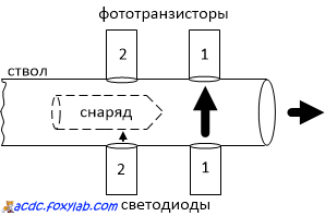

When the light flux of sensor 2 (closest to the coil) is blocked, red (" RED") LED, and when sensor 1 is blocked - green (" GREEN").
This signal is converted to a level of tenths of a volt (dividers from resistors R1,R3 And R2,R4) and is fed to two channels of the linear (not microphone!) input of the computer sound card using a cable with two plugs - a plug connected to the Gaussian connector, and a plug plugged into the socket of the computer sound card:
voltage divider:
LEFT- left channel; RIGHT- right channel; GND- "Earth"
plug connected to the gun:
5 - left channel; 1 - right channel; 3 - "ground"
plug connected to the computer:
1 - left channel; 2 - right channel; 3 - "ground"
It is convenient to use for signal processing free program Audacity().
Since on each sound card input channel a capacitor is connected in series with the rest of the circuit, the sound card input is actually R.C.-chain, and the signal recorded by the computer has a smoothed form: 
Characteristic points on the graphs:
1 - flight of the front part of the projectile past sensor 1
2 - flight of the front part of the projectile past sensor 2
3 - flight of the rear part of the projectile past sensor 1
4 - flight of the rear part of the projectile past sensor 2
I determine the initial velocity of the projectile by the time difference between points 3 and 4, taking into account that the distance between the sensors is 1 cm.
In the given example, with a digitizing frequency $f$ = 192000 Hz for the number of samples $N$ = 160, the projectile speed $v = ((l f) \over (N)) = ((1920) \over 160)$ was 12 m/s .
The speed of a projectile leaving the barrel depends on its initial position in the barrel, specified by the displacement of the rear part of the projectile from the edge of the barrel $\Delta$: 
For each battery capacity $C$, the optimal projectile position ($\Delta$ value) is different.
For the projectile described above and a battery capacity of 370 uF, I got the following results:
With a battery capacity of 150 µF the results were as follows:
The maximum projectile speed was $v$ = 21.1 m/s (at $\Delta$ = 10 mm), which corresponds to an energy of ~ 0.5 J
-
When testing a ferrite rod projectile, it turned out that it requires a much deeper location in the barrel (a much larger $\Delta$ value).
Gun laws
In the Republic of Belarus, products with muzzle energy ( muzzle energy) no more than 3 J
purchased without appropriate permission and are not registered.
IN Russian Federation products with muzzle energy less than 3 J
are not considered weapons.
In the UK, products with muzzle energy are not considered weapons. no more than 1.3 J.
Determination of capacitor discharge current
To determine the maximum discharge current of a capacitor, you can use a graph of the voltage across the capacitor during discharge. To do this, you can connect to a connector to which the voltage on the capacitor, reduced by $n$ = 100 times, is supplied through a divider. Capacitor discharge current $i = (n) \cdot (C \cdot ((du) \over (dt))) = (((m_u) \over (m_t)) C tg \alpha)$, where $\alpha$ - the angle of inclination of the tangent to the capacitor voltage curve at a given point.
Here is an example of such a discharge voltage curve on a capacitor: 
In this example $C$ = 800 µF, $m_u$ = 1 V/div, $m_t$ = 6.4 ms/div, $\alpha$ = -69.4°, $tg\alpha = -2 .66 $, which corresponds to the current at the beginning of the discharge $i = (100) \cdot (800) \cdot (10^(-6)) \cdot (1 \over (6.4 \cdot (10^(-3) ))) \cdot (-2.66) = -33.3$ amperes.
To be continued
.
In this article, Konstantin, How-todo workshop, will show you how to make a portable Gauss cannon.
The project was done just for fun, so there was no goal to set any records in Gausso construction.


We charge the capacitor high voltage and discharge it onto a coil of copper wire located on the trunk.
When current flows through it, a powerful electromagnetic field is created. The ferromagnetic bullet is drawn into the barrel. The capacitor's charge is consumed very quickly and, ideally, the current through the coil stops flowing the moment the bullet is in the middle.

Before we move on to assembly, we should warn you that you need to work with high voltage very carefully.
Especially when using such large capacitors, this can be quite dangerous.

Firstly, because of the simplicity. The electronics in it are almost elementary.
When manufacturing a multi-stage system, you need to somehow switch the coils, calculate them, and install sensors.


I had to paint halfway out of the window.


Therefore, we take a AA battery.


