A gable roof is one of the most common and versatile roofing structures for buildings. for various purposes. They can be made as cold for non-residential attic spaces, and insulated for attic rooms.
Important. The house has two main architectural elements that play a decisive role in the durability and safety of operation: the foundation and the roof. During their design, it is necessary to strictly comply with all the requirements of building codes and regulations.
Only professionals can design and build a rafter system. They must have deep theoretical knowledge and great practical experience performing such work, only practice allows you to make optimal decisions during construction.

Each house has its own individual characteristics, each batch of lumber differs in strength, each load-bearing unit can be manufactured and fixed different ways. All this affects the stability of the rafter system, increases or decreases the estimated cost of the roof, etc. It is necessary to achieve such an option so that the rafter system is as simple as possible to construct and at the same time reliable and cheap.

There are many different opinions from inexperienced developers about how to choose the distance between the rafters. Some seriously give advice on choosing this parameter for each type roofing material: natural or artificial piece tiles, metal tiles and corrugated sheets, soft bitumen or slate coverings. In fact, none of this is true; architects never specify the type of roofing in the initial data when calculating the pitch of the rafter system.
The physical properties of roofing materials, together with other factors, influence not the distance between the rafters, but their dimensions and additional structural elements of the rafter system to increase the stability of the structure, including:

In the roof structure wooden house a bunch of various elements, each of which performs its own function and is fixed in a certain way. To find out in detail what elements the roof of a wooden house consists of,. You will find not only descriptions of the elements, but also the best practical tips!
Before starting calculations, engineers have initial data (technical specifications) for the entire system; taking these values into account, other parameters are calculated. The initial data also includes the pitch of the rafters; it is known before the design begins and does not change in the final project. What exactly affects this parameter?
| Factors affecting the distance between rafters | Short description |
|---|---|
| This factor has an effect only if it is planned to make the roof insulated. IN terms of reference The design must indicate the type and size of insulation used, but they vary. Eg, standard width foam and pressed mineral wool is 60 cm. In order to eliminate the formation of cold bridges, facilitate and speed up the process of installing insulation and minimize the amount of unproductive waste, the span between the rafters should be within 56–58 cm. Roll mineral wool can have a width from 120 cm to 100 cm. Accordingly, a different step is required for their installation rafter legs. |
| How longer distance, the more load each rafter leg takes. This affects its size and the total amount of lumber for the roof. Currently, wood belongs to a very expensive category of building materials; it is necessary to reduce consumption. This is done both by using additional supports of the rafter system for optimal load distribution, and by adjusting the number of rafter legs, which allows you to reduce the cross-section of the roof elements and save expensive boards. |
| Each house has its own architectural features. This refers to the location and number of chimneys and ventilation outlets, the layout of attic spaces, manufacturing materials load-bearing walls, the presence of a wooden Mauerlat or concrete reinforcing belt. Rafters cannot be located above chimneys and ventilation pipes, interfere with installation skylights etc. Such nuances must be thought through during the design of the structure; they also affect the distance between the rafters. |
Important. The pitch of the rafter legs is measured between the axes; when choosing the final parameter, you need to take into account the thickness of the boards. For installation of insulation, the distance between the side planes, and not the axes of the rafters, is important.
This issue needs to be discussed in detail; quite a few developers do not fully understand the problem. To answer, you need to know the fundamental differences between materials and their effect on the distance and calculation of rafters. Let us emphasize that we do not mean performance characteristics roofing coverings or their design appearance, namely structural and physical differences.


All these materials have fundamentally different methods of fixation to the rafter system. But they do not have any effect on the pitch of the rafters.


Roof tiles
As mentioned above, the distance between the rafters is set to initial stage and depends on the characteristics of the insulation. They influence another one of them important parameter– width of the boards.

She must take into account minimum thickness insulation layer taking into account the climatic zone of the building's location. If in cold regions the insulation should have a thickness of 20 cm or more, then for warmer climates 10 cm of insulation is sufficient. Accordingly, the width of the rafter board is from 20 cm to 10 cm.

Practical advice. You always need to consider the cost of lumber. There are options when it is much more profitable for the rafter legs to use boards 10 cm wide, and increase the depth of the niche for the insulation by adding ordinary thin low-quality ones. But in all cases, the main sizing criterion is the ability to support maximum design loads.
The calculation of rafters is carried out in several stages.
Several types of loads act on the roof slope, they have different meaning and its characteristics of influence on the strength of the system.

For lightweight metal sheets, this is not necessary.

The fact is that the roof is a particularly important structural element of the building, and they have a safety margin of at least 140%. This means that the structure can withstand loads almost one and a half times greater than the calculated ones. The maximum load on the roof is created by snow and wind. The values of these forces are measured in hundreds of kilograms, and the mass of metal sheets is only a few kilograms per square meter. The safety factor completely covers the possible increase in effort.


The maximum permanent and temporary loads are summed up and increased by approximately 40% to create a safety margin for all load-bearing elements. The safety factor can be taken into account using another method. After all engineering calculations have been completed, the linear parameters of the rafters are determined, in the final version they are multiplied by a factor of 1.4, the results are used when creating working drawings of the rafter system. It doesn’t matter which method you use, the main thing is to maintain the accuracy of mathematical calculations, and only a specialist with a special technical education can perform them.
The methodology is prescribed in SNiP 2.01.07-85, it includes changes to some formulas adopted in 2008. Before taking into account the distance between the rafters, you should find out all the loads acting on them.
Snow guard
Engineers use the formula

Formula 1. Definition snow load
We have already mentioned that the normative load may differ significantly from the actual load, and therefore it is recommended to use more up-to-date data. As for the roof inclination angle α, this parameter is set in the original technical conditions for the design of the rafter system. The coefficient µ is determined by the formula

Formula 2. Definition of µ
One component of several forces on the rafters has been determined; now we should move on to the remaining types of loads.
Important. Please note that snow loads, depending on the climatic region, range from 120–180 kg/m2. Now it should be clear why the weight of light roofs can be ignored; their forces are approximately 5–7 kg/m2, this is within the limits of mathematical error. In addition, a safety factor is applied. 40% of 180 kg is 72 kg, this value is much greater than the mass metal roofs and has already been taken into account during strength calculations of rafters.
These forces can reach significant values and are necessarily taken into account when calculating the parameters of the rafter legs. In this case, two types of wind loads are distinguished. When the slopes are tilted more than 30°, the wind tries to overturn them and puts great force on the leeward side of the roof. If the slope is small, then due to differences in the speed of air flows, lift, tearing the roof off the mauerlat. Wind loads are determined by the formula

The height wind pressure coefficient includes several factors. All of them have complex calculation methods, which are performed by competent thermodynamic engineers.
To facilitate calculations in regulatory documents There is a ready-made table, the specific coefficient is selected depending on:
The aerodynamic coefficient can be greater than one or less than one. In the first case, the wind load increases, in the second it decreases slightly. For most buildings, simplified calculations are made for wind loads; it is assumed that the coefficient is 0.8.

Taking into account the characteristics of the lathing and the materials used to make the rafter legs, their total mass can increase the load on the system within the range of 30–50 kg/m2. As already mentioned, this parameter can be ignored. The large safety factor makes the roofs universal; they can be covered with any type of roofing materials.
The distance between them is included in the design specifications, is a stable value and is specified in the design specifications. Next, you should find out the linear dimensions of the rafters so that they can withstand the maximum possible forces during operation. Distributed load on linear meter legs is determined by the formula

We have all the initial data for calculating the distributed load.
Now you can proceed to selecting the optimal cross-section of the rafter leg. In this case, you should be guided by the GOST 24454-80 table, which indicates the standard dimensions of lumber (thickness and width).
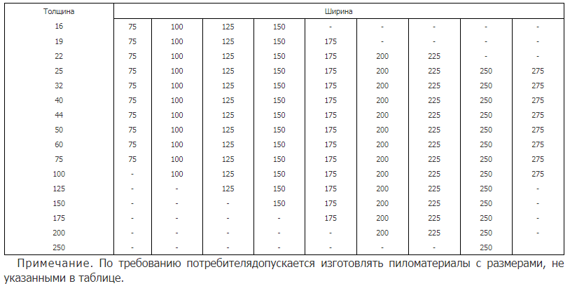
Nominal dimensions of the thickness and width of edged lumber with parallel edges and the thickness of unedged and edged lumber with non-parallel edges
You should definitely familiarize yourself with the table; this is necessary to understand the methodology for selecting boards. For example, with a thickness of 16 mm, the maximum width of the board is 150 mm, and with a thickness of 75 mm, the maximum width increases to 275 mm.
You need to set the section width of the board and, taking this parameter into account, calculate the height. The formula used is

It is suitable for cases where the roof slope is α< 30°.
If the slope angle α > 30°, then you need to use the formula

Depends on the quality of lumber and type of wood, taken from tables state standards. The quality of lumber plays a decisive role in the bending resistance of lumber.


For example, if for the first grade of pine Rben = 140 kg/cm2, then for the third grade this parameter is reduced to 85 kg/cm2. Standards strictly regulate the bending radius of the roof; if it is too small, then there is a high risk of leaks due to damage to the integrity of the roof coverings. For all roof elements, the deflection value cannot exceed L (length of the working section)/200.
SNiP has a formula for checking the condition under which the deflection does not exceed the established standards

If the amount exceeds one, then it is necessary to increase the thickness or width of the rafter leg.
The number of rafters is known; this value is always determined taking into account the required distance between them. In our case, the step is 80 cm, the slope angle is 35°, the length of the working area is 280 cm. Rafter system made of pine, the bending radius of this first grade material is 140 kg/cm2. Piece will be used as roofing material cement-sand tiles. This is a very heavy material, its weight is recommended to be taken into account. The weight of a square meter of tiles reaches 50 kg. Now all the initial data are known, you can begin the calculations.
Taking into account the climatic zone, the total wind and snow load is 253 kg/m2, to which the weight of the tiles should be added, the total is 303 kg/m2. The distributed load on the rafter is calculated using the formula and in our case is 242 kg/m2. It is planned to make the rafters 5 cm thick; you need to find their width.
Apply the formula
This particular formula is used due to the fact that the angle of inclination of the slope is more than thirty degrees. Now it remains to check whether the maximum permissible deflection radius of the rafter will not be exceeded. If the value is less than one, everything is normal. If it is more than one, then it is necessary to increase the linear dimensions of the boards.
This need arises very rarely and mainly concerns non-residential premises. For example, a developer already has boards for making a rafter system; he needs to know at what distance to fix the rafters so that the roof can withstand the design loads. That is, you need to do the reverse calculation. If in a standard situation the distance is known and the dimensions of the boards are selected taking these parameters into account, then in the second case the opposite is true. The dimensions of the rafter boards are known; the pitch of the rafters needs to be determined. This is done in this order.

Knowing the total load on the roof and maximum load For one rafter, by simple arithmetic we determine the number of rafter legs. Of course, all roundings are made upward; an excess safety margin will never harm the rafter system. The last stage - the length of the roof slope is divided by the minimum number of rafters and the distance between them is obtained. Rounding should be done in the direction of decreasing the step.
A gable roof is formed on the basis of a frame that combines the simplicity of the device and unsurpassed reliability. But the roof skeleton of two rectangular slopes can boast of these advantages only if the rafter legs are carefully selected.
It’s worth starting the calculations if you understand that the rafter system of a gable roof is a complex of triangles, the most rigid elements of the frame. They are assembled from boards, the size of which plays a special role.
The formula will help determine the length of durable boards for the rafter systema²+b²=c², derived by Pythagoras.
The length of the rafter can be found by knowing the width of the house and the height of the roof
The parameter “a” indicates the height and is independently selected. It depends on whether the under-roof space will be residential, and also has certain recommendations if an attic is planned.
Behind the letter "b" is the width of the building, divided in two. And “c” represents the hypotenuse of the triangle, that is, the length of the rafter legs.
Let’s assume that the width of half the house is three meters, and it was decided to make the roof two meters high. In this case, the length of the rafter legs will reach 3.6 m (c=√a²+b²=4+√9=√13≈3.6).
You should add 60–70 cm to the figure obtained from the Pythagorean formula. The extra centimeters will be needed to carry the rafter leg beyond the wall and make the necessary cuts.
The six-meter rafter is the longest, so it is suitable as a rafter leg
The maximum length of a beam used as a rafter leg is 6 m. If a durable board of greater length is required, then they resort to the fusion method - nailing a section from another beam to the rafter leg.
For various elements of the rafter system, there are standard sizes:
The thickness of each part of the supporting roof structure is determined by the load that it will experience.
A beam with a section of 10x20 cm is ideal for creating a rafter leg
The cross-section of the rafter legs of a gable roof is affected by:
The most significant effect on the cross-section of the rafter legs is the pitch of the rafters. An increase in the distance between the beams entails increased pressure on the supporting structure of the roof, and this obliges the builder to use thick rafter legs.
The pressure on the rafter legs can be constant or variable.
From time to time and with varying intensity, the supporting structure of the roof is affected by wind, snow and precipitation. In general, the roof slope is comparable to a sail that is under pressure natural phenomena may tear.
The wind tends to overturn or lift the roof, so it is important to make all the calculations correctly
The variable wind load on the rafters is determined by the formula W = Wo × k x c, where W is the wind load indicator, Wo is the value of the wind load characteristic of a certain area of Russia, k is a correction factor determined by the height of the structure and the nature of the terrain, and c is the aerodynamic factor coefficient.
The aerodynamic coefficient can vary from -1.8 to +0.8. A negative value is typical for a rising roof, while a positive value is typical for a roof on which the wind presses. In a simplified calculation with a focus on improving strength, the aerodynamic coefficient is considered equal to 0.8.
Calculation of wind pressure on the roof is based on the location of the house
The standard value of wind pressure is determined from map 3 of Appendix 5 in SNiP 2.01.07–85 and a special table. The coefficient taking into account the change in wind pressure with height is also standardized.
It's not just the terrain that affects wind loads. Great importance has a residential area. Behind the wall of tall buildings the house is in almost no danger, but in open space the wind can become a serious enemy for it.
The snow load on the rafter system is calculated using the formula S = Sg × µ, that is, the weight snow mass per 1 m² is multiplied by a correction factor, the value of which reflects the degree of roof slope.
The weight of the snow layer is indicated in SNiP “Rafter Systems” and is determined by the type of terrain where the building is built.
The snow load on the roof depends on where the house is located
The correction factor, if the roof slopes tilt less than 25°, is equal to one. And in the case of a roof slope of 25–60°, this figure decreases to 0.7.
When the roof is sloped more than 60 degrees, the snow load is discounted. Still, snow rolls off a steep roof quickly, without having time to have a negative impact on the rafters.
Loads acting continuously are considered to be weight roofing pie, including sheathing, insulation, films and Decoration Materials for arranging an attic.
Roofing pie creates constant pressure to the rafters
The weight of the roof is the sum of the weight of all materials used in the construction of the roof. On average it is 40–45 kg/sq.m. According to the rules, per 1 m² of rafter system there should not be more than 50 kg of roofing material weight.
To ensure that there is no doubt about the strength of the rafter system, it is worth adding 10% to the calculation of the load on the rafter legs.
| Type of roofing finish | Weight in kg per 1 m² |
| Rolled bitumen-polymer sheet | 4–8 |
| Bitumen-polymer soft tiles | 7–8 |
| Ondulin | 3–4 |
| Metal tiles | 4–6 |
| Corrugated sheeting, seam roofing, galvanized metal sheets | 4–6 |
| Cement-sand tiles | 40–50 |
| Ceramic tiles | 35–40 |
| Slate | 10–14 |
| Slate roofing | 40–50 |
| Copper | 8 |
| Green roof | 80–150 |
| Rough flooring | 18–20 |
| Lathing | 8–10 |
| The rafter system itself | 15–20 |
How many rafters will be needed to arrange the frame of a gable roof is determined by dividing the width of the roof by the pitch between the beams and adding one to the resulting value. It indicates an additional rafter that will need to be placed on the edge of the roof.
Let's say it was decided to leave 60 cm between the rafters, and the length of the roof is 6 m (600 cm). It turns out that 11 rafters are needed (including the additional timber).
The rafter system of a gable roof is a structure made from a certain number of rafters
To determine the distance between the beams of the supporting roof structure, you should pay close attention to such points as:
It is customary to place rafters at 90–100 cm intervals when choosing a lightweight roofing material
A normal step for rafter legs is 60–120 cm. The choice in favor of 60 or 80 cm is made in the case of constructing a roof inclined at 45˚. The same small step should be taken if you want to cover wooden frame roofs with heavy materials such as ceramic tiles, asbestos-cement slate and cement-sand tiles.
Calculation of the rafter system comes down to establishing the pressure on each beam and determining the optimal cross-section.
When calculating the rafter system of a gable roof, proceed as follows:
| Board thickness - section width (B) | Board width - section height (H) | ||||||||
| 16 | 75 | 100 | 125 | 150 | - | - | - | - | - |
| 19 | 75 | 100 | 125 | 150 | 175 | - | - | - | - |
| 22 | 75 | 100 | 125 | 150 | 175 | 200 | 225 | - | - |
| 25 | 75 | 100 | 125 | 150 | 175 | 200 | 225 | 250 | 275 |
| 32 | 75 | 100 | 125 | 150 | 175 | 200 | 225 | 250 | 275 |
| 40 | 75 | 100 | 125 | 150 | 175 | 200 | 225 | 250 | 275 |
| 44 | 75 | 100 | 125 | 150 | 175 | 200 | 225 | 250 | 275 |
| 50 | 75 | 100 | 125 | 150 | 175 | 200 | 225 | 250 | 275 |
| 60 | 75 | 100 | 125 | 150 | 175 | 200 | 225 | 250 | 275 |
| 75 | 75 | 100 | 125 | 150 | 175 | 200 | 225 | 250 | 275 |
| 100 | - | 100 | 125 | 150 | 175 | 200 | 225 | 250 | 275 |
| 125 | - | - | 125 | 150 | 175 | 200 | 225 | 250 | - |
| 150 | - | - | - | 150 | 175 | 200 | 225 | 250 | - |
| 175 | - | - | - | - | 175 | 200 | 225 | 250 | - |
| 200 | - | - | - | - | - | 200 | 225 | 250 | - |
| 250 | - | - | - | - | - | - | - | 250 | - |
Let us assume that α (roof inclination angle) = 36°, A (distance between rafters) = 0.8 m, and Lmax (working section of the rafter leg of maximum length) = 2.8 m. First grade pine material is used as beams , which means that Rben = 140 kg/cm².
Cement-sand tiles were chosen to cover the roof, and therefore the weight of the roof is 50 kg/m². The total load (Q) experienced by each square meter is 303 kg/m². And for the construction of the rafter system, beams 5 cm thick are used.
The following computational steps follow from this:
In the table standard sizes you need to find a cross-sectional height of the rafters that is close to 15.6 cm. A suitable parameter is 17.5 cm (with a section width of 5 cm).
This value fully corresponds to the deflection indicator in regulatory documents, and this is proven by the inequality 3.125·Qr·(Lmax)³/B·H³ ≤ 1. Substituting into it the values (3.125·242·(2.8)³ / 5·(17, 5)³), we will find that 0.61< 1. Можно сделать вывод: сечение пиломатериала выбрано верно.
Calculating the rafter system of a gable roof is a whole complex of calculations. In order for the beams to cope with the task assigned to them, the builder needs to accurately determine the length, quantity and cross-section of the material, find out the load on it and find out what the pitch between the rafters should be.
The distance between the rafters (rafter legs) is called the rafter pitch. When arranging a roof, it is customary to use a rafter pitch of no more than 100 and no less than 60 cm. The reliability of the roof structure depends entirely on how correctly the distance is calculated.
Incorrect determination of the loads on the rafters and the parameters of the materials used as them can cause deformation of not only the roof, but the entire building. The roof may collapse and cause the walls to collapse. Considering this, the design calculation of the rafter system must be given the same close attention as the overall design of the building.

As an example, let's take a slope 30 m long and a distance between the rafters of 0.6 m.
50 + 1 = 51 - 51 rafters will be required to build the roof.
Then we determine the step between the beams that will be used as a supporting structure:
30: 51 = 0.58 m - the distance between the axes of the beams that will be installed on the roof slope as rafters.
This example shows general methodology calculation of the supporting structure, but does not take into account the specifics of a particular roofing material. Experts recommend calculating the distance based on the characteristics of roofing coverings.
In addition, calculations should be performed taking into account the materials from which the rafter system of the house will be made. Here the step largely depends on both the type of material and its dimensions.
Return to contents

Although ceramic tiles is one of the elite and environmentally friendly roofing materials, its installation is associated with certain difficulties. And the main one is a large mass. Thus, the weight of ceramic tiles is almost 10 times the weight of metal tiles. This means that for every m 2 of the structure a pressure of 40 to 60 kg will be exerted. These conditions imply the creation of a reinforced load-bearing system capable of supporting the weight of the roof.
To create a rafter system for a roof made of ceramic tiles, a beam with a cross-section of at least 5x15 cm, or better yet 6x18 cm, is usually used. The moisture content of the wood should not exceed 15%.
The distance between the beams depends on the slope of the slope and the length of the rafters. So, the steeper the roof, the greater the distance between the rafters will be. If, with a slope slope of 15 o, the step is 80 cm, then with a slope of 75 o it will be equal to 130 cm. Long bars will be located on maximum distance from each other, and short ones - at the minimum.
In order for the installation of ceramic tiles to be carried out correctly, the pitch of not only the rafter legs, but also the sheathing is important. When creating a house design, it is necessary to take into account the parameters of each roofing element(V in this case tiles). Typically, tile tiles do not exceed a length of 40 cm, and during installation they overlap with the previous row by about 9 cm. This determines the pitch of the sheathing, which should be no less than 31 and no more than 35 cm.
This indicator can also be determined according to the following scheme:
Return to contents

Installation of metal tiles does not require reinforcement of the supporting structure due to its low weight. The wood will not resist the loads exerted, which means that the step between the beams may not be wide. So, with metal roofing, the rafters can be located at a distance of 60-95 cm from each other.
Corrugated sheeting is another roofing material that is lightweight. And according to other characteristics, corrugated sheeting is as close as possible to metal tiles. Therefore, the pitch of the rafter legs is similar to the above - from 60 to 90 cm.
Distance parameters determine the characteristics of building materials. For example, if a board less than 10 cm wide is used to construct a structure on the roof, the distance should be reduced to 50 cm.
Do not forget about the distance between the elements of the sheathing, which can range from 0 to 400 cm. The pitch of the sheathing is selected taking into account the grade of the corrugated sheet and the slope of the slope. For example, a profiled sheet of grade C-21 with a thickness of 0.5 to 0.7 mm with a roof slope of more than 15 o should be attached to the sheathing, the pitch of which will be no more than 65 cm.
The content of the articleWhen building a roof, the first thing to choose is the type of rafter system. This means that the rafters must be hanging or layered, or the entire rafter system will consist of both rafters, i.e., combined. It is not difficult to calculate the distance between the rafters, knowing the magnitude of the loads that will act on the entire roof.
Loads can be temporary or permanent. Constant loads include:
Temporary loads include: weight of snow cover, weight of a person during production roofing works and roof maintenance during operation, wind load and the weight of possible water flows in the summer.
The distance between the roof rafters is also calculated based on the selected material and the cross-section of the rafters. All calculations are carried out at the house design stage by specialists from design organizations. To do this, they use reference documents and building codes that regulate this or that rafter pitch, sheathing pitch and other calculated values.
When building a private house, rarely does anyone order a project where, based on calculations, it is recommended what distance between the rafters should be maintained. Most often, developers rely on the experience of the craftsmen and trust them to carry out all the calculations on site. However, there are those who want to calculate the rafter system themselves and build the roof themselves.
In this case, they must first decide on the type of roof, choose what kind of attic it will be - heated residential or cold, since the type of rafter system and the calculation of the distance between the rafters directly depend on these parameters
Calculation for pitched roof- simplest. The rafter system does not provide racks and braces - only the rafters themselves. This type of roof is most often installed on utility rooms, garages, bathhouses, etc.
The pitch of the rafters of a pitched roof is presented in the table below and depends on the cross-section of the timber:
If the developer wants to independently calculate the loads on the rafter system, it will be useful for him to familiarize himself with documents such as SNiP 2.01.85 “Loads and impacts” and “Changes from SNiP 2.01.85”, which contains maps of the climatic regions of Russia.


The material chosen for the construction of the rafter system is coniferous wood, the humidity of which is 20-22%. Boards, beams and other types of lumber must be smooth without curling, rot, knots or blue stains.
All wooden elements should be treated with antiseptics and fire retardants to protect the wood from rotting and fire. The material used, the length of the rafters and the cross-section of the timber also affects the calculations (see table):

The pitch of the rafters is nothing more than the distance between the rafter legs. As a rule, for residential private houses this figure is 0.6-1.0 m.
The pitch of the rafters is influenced by a significant number of factors. Calculation required quantity rafter legs are produced in the following way:
For example: length roof slope is 16 meters, and the pitch between the rafters is 0.6 meters. Therefore, 16/0.6 + 1 = 27.66 = 28 meters (rafters are necessary for the installation of the slope)
The greater the slope angle, i.e., the steeper the roof, the larger the pitch of the rafters can be made. This is explained by the fact that the load on steep roofs is not distributed over the entire roof plane, but is mostly transferred to the load-bearing walls.
Ceramic tiles are a material that has a decent weight. Therefore, to install a tile roof, you should calculate the cross-section and length of the rafters, taking into account that one square meter of ceramics weighs almost ten times more than the weight of metal tiles.
The higher the roof, the wider the rafter spacing can be. For example, with a slope angle of 15 degrees, the step will be 80 cm, and if the slope angle increases to 75 degrees, the distance between the rafter legs will increase to 1.3 m.
Another circumstance affects the pitch of the rafters - the length of the rafter legs. The longer they are, the shorter their step. This is explained by the fact that when maximum length rafters create increased deflection loads. They can be reduced by installing a system of supporting posts, struts and other elements of the rafter system, which take on part of the loads from the rafters.

The rafter system for metal tiles is not much different from others truss structures. But due to the fact that it weighs several times less than ceramic tiles, rafters and all other elements of the roof structure can be made with a smaller margin of safety, i.e., a smaller cross-section. The difference in weight of clay and metal tiles is about 35 kg per 1 m2.
 The rafter spacing for metal tiles is usually 0.6-0.9 m. Metal tiles are widely used for covering country houses, which often provide attic rooms, so the roof is made insulated. The pitch of the rafters in such structures is adjusted to the size of the insulation, which is inserted between the rafter legs.
The roofs of modern private houses can have different configurations. The most popular type of roofing is gable. Owners of suburban areas consider reliability, quite attractive, to be the undoubted advantage of such a roof. appearance and efficiency. The design of this type of roof is extremely simple, and therefore it will not be difficult to erect it, even with your own hands.
Lightweight and durable sheet materials- this is what is most often sheathed gable roof. Corrugated sheeting, for example, is simply ideal for such a design. This type of roof protects well inner space at home, lasts a long time and is inexpensive. Of course, the procedure for constructing a rafter system under corrugated sheets, like under any other material, has some of its own characteristics.
How is a gable roof assembled? under the corrugated sheeting it will turn out to be reliable, and the roof itself will be neat only if it is first prepared detailed project designs. When developing the latter you need:
determine the angle of inclination of the slopes;
decide on the type of materials needed for construction;
make detailed drawings of the frame indicating the method of connecting all nodes.
If all these operations are completed without errors, the end result will be a strong gable roof. A rafter system for corrugated sheets, a drawing of which can be made using, for example, special software on a computer, will last as long as possible.

This step should never be skipped when drawing up a roof project. Correctly performed calculations are the key to the end result being a durable gable roof. The rafter system for corrugated sheeting (a photo of the assembly of such a frame can be seen below) is mounted taking into account the following parameters:
weights of all materials used;
The values of the last two indicators can be found in special tables developed specifically for each specific region.
All figures obtained as a result of calculations must be added and multiplied by a reliability factor of 1.1. Having calculated the rafter system of a gable roof in this way, it will be possible to determine, first of all, the type of materials required for assembly. Also, taking into account the final load indicator, choose optimal angle location of roof frame supports.
In addition to the load, when choosing this indicator, the characteristics of the roofing material itself should also be taken into account. The angle of inclination of the slopes can be any, but not less than 12 degrees. If you make the roof flatter, it will leak later. At the same time, the sheets themselves will begin to sag under the weight of snow in winter. That is, the roof will have to be constantly repaired. And this, of course, is additional costs.

IN Middle lane In Russia, taking into account wind and snow loads, it is almost universally allowed to erect roofs with slope angles of 30-45 degrees. This option is ideal for corrugated sheets. In the southern regions, the angle of inclination of the slopes of the roofs of houses may be smaller, and in the northern regions, on the contrary, it can be greater.
Among other things, when choosing a method for installing rafters, it is worth considering exactly how the attic will be used in the future. If it is intended to be insulated and equipped as a living space, it is better to make the slopes steeper. But of course, in this case, erecting a roof will cost a little more, since you will have to use large quantity materials.
What specific materials can such a gable roof be constructed from? with your own hands - in any case, it is a responsible matter, and must, of course, be as reliable as possible. But one of the advantages of corrugated sheeting is that it is light in weight. Therefore, it is not necessary to use any special, very durable materials to assemble the frame for it. For such roof rafters, a standard 150x100 mm beam is quite suitable. It is advisable to use lumber of a larger cross-section only if the attic is intended to be used as a living space. Rafters for such a roof are usually made of 200x100 mm timber.
The sheathing can be assembled from edged boards 30x100-150 mm. Too wide lumber cannot be used in this case. After some time, such boards will simply dry out and become severely warped, which will have an extremely negative impact on the reliability of the roof. Under the Mauerlat it is better to take a thicker beam - 200x150 mm.

Too often, it is also not necessary to install frame supports under light metal sheets. The optimal distance between the rafters of a gable roof under corrugated sheeting is 60-80 cm. As for the sheathing, the pitch between its elements is selected taking into account the type of sheets used. So, for thick material 0.6-0.7 mm with a profile height of 3.5 cm, boards can be stacked at a distance of up to 1.5 m from each other.
For standard N-grade corrugated sheeting, the lathing pitch is usually 60-70 cm. The same distance is suitable for CH material. Thin sheet C is mounted on a sheathing, stuffed in increments of 10 cm or on a continuous sheet of 12 mm plywood or OSB sheets.
The roof frame of the house is mounted in several steps:
Mauerlat is installed;
rafters are installed;
if necessary, insulation is installed;
the rafters are covered with waterproofing;
the sheathing is stuffed.
They begin assembling such a structure as a gable roof made of corrugated sheets with their own hands by installing this particular element. The Mauerlat is mounted on top of the building frame. As a basis for the rafter system, this element is used only on brick, monolithic or block walls. In cobblestone and chopped ones, its role is played by the upper crown. The timber should be secured to the walls using anchor bolts. You can also use steel dowels, galvanized wire with a thickness of 5 mm or staples.

The supports themselves can be attached to the Mauerlat in two ways. For brick, block and monolithic houses Rigid fixation technology is used. In this case, they are attached to the Mauerlat using galvanized steel corners and self-tapping screws or a “knot” of three nails (one in the upper plane, two on the sides).
On chopped and cobblestone walls, the rafters are fastened using the sliding method. The fact is that such houses shrink strongly during the first time after construction. Therefore, a rigidly fixed roof frame can simply fail in the future. At sliding method When installing rafters, special fixing elements, “sleds,” are used to ensure the mobility of the supports in a small range.
The supporting elements of the frame must be installed correctly. In this case, you will get a neat symmetrical gable roof. The rafter system for corrugated sheeting, like for any other material, must be assembled using a template. In this case, all legs will have the same length. For gable roofs made of corrugated sheets, either simple straight rafters (with the edge cut at the required angle) or an option with mounting sockets for the Mauerlat can be used. The frame supports are usually attached to each other at the top using special thick steel plates.
The end trusses are always installed first. Next, a cord is stretched between their highest points. Then, focusing on it, intermediate trusses are installed. On large roofs, a ridge girder on supports is pre-installed between the outer paired rafters. The latter are securely fixed to the floor beams.
If the attic is intended to be made habitable, it will, of course, have to be insulated during the construction of the roof. On corrugated roofs, mineral wool is most often used for this purpose. To support it, a wire is stretched from the attic side onto the rafters. The mats themselves are installed by surprise.
The waterproofing is sewn onto the rafters with a slight sag (2 cm). Do not stretch the film too much. Otherwise, when the frame moves, it may simply tear. The waterproofing strips are installed horizontally from bottom to top with an overlap of at least 10-15 cm.

The support boards under the corrugated sheets are attached to the rafters using nails with a diameter of about 3-3.5 mm. The length of the fasteners must exceed the thickness of the elements being fixed by two times. Assembly begins from the cornice. The boards should be fastened to each rafter with two nails. The last two rows at the ridge are filled without a gap.
After the sheathing has been assembled, you can begin covering the frame with the corrugated sheet itself. On final stage the roof gables are covered with boards.
Wood is a material that is very easy to process and at the same time quite durable. That is why the rafter system of a gable roof is most often assembled with your own hands from timber and boards. However, unfortunately, lumber cannot boast of a very long service life. Sooner or later, the roof of the building begins to dry out or rot. Therefore, before assembling it, timber and boards must be treated with special compounds that increase their moisture resistance.
Another disadvantage of wood is flammability. To minimize the risk of fire, the lumber used to construct the building frame should, among other things, be carefully treated with a product that increases its fire resistance.

This is how the gable roof is assembled. The rafter system under the corrugated sheet, as you can see, is mounted simply. Nevertheless, installing a roof frame is a very responsible undertaking. If any technology is violated, the owners of the house will inevitably have problems with leaks and the need for replacement. individual elements etc. Therefore, it is worth approaching the assembly of the roof truss system with maximum responsibility.


