A do-it-yourself crane will always come in handy on the farm for anyone who has a summer house or those who live in a private house. It will be especially needed by those owners who are not afraid of various independent construction and repair work. Renting such equipment, let alone purchasing it, will cost a considerable amount. And do crane DIY, in fact, is quite simple - you will learn about this in this article. Try to understand the proposed instructions step by step, performing all the work, and you will get an excellent tool for household use.
For further work you will need the following materials:
Most of the necessary and useful tools It is quite possible to make it yourself, thereby saving the family budget. In general, such a structure is assembled very simply and as quickly as possible. The algorithm described below will help even an inexperienced master. The main thing is to select all the necessary parts and working tools for the future structure.
Important! Ultimately, the resulting structure will weigh approximately 250-300 kg. At the same time, it will be quite compact. A self-built crane will not have a very high lifting capacity (approximately 200 kg), however, this will be more than enough for most home construction or repair work.

Let's move on to the algorithm for making a mini-faucet with your own hands:
Important! Both parts must fit tightly into the bearing. Thus, both parts are connected.
Important! To tighten the bolt that will be attached to the base of the platform, it will be necessary spanner wrench with an extension cord, as well as two washers - a Grover and a flat one.
Important! As a platform, you can use a 1.5-meter I-beam, the width of which will be approximately 18 cm.
Important! The entire assembly must be carried out in a lying position, and when completed the structure must be raised so that it is in an upright position on some support.
Almost any construction site You can’t do without special equipment, especially a construction crane. It becomes an indispensable assistant when it is necessary to lift heavy loads to different heights.
Most people associate this technique with huge size, but there are many types of taps that are distinguished by their ergonomics and compactness.
You can even do some options yourself, saving personal savings during construction. In this article we will look at how to collect homemade faucet"Pioneer" for building a house.
Mini cranes are in great demand. They are used during construction and repair work. Modern manufacturers offer innovative solutions in the manufacture of their products.
These devices are different:
Thanks to the availability various attachments, with this technique you can carry out various manipulations.
Mini cranes, both purchased and assembled at home, are capable of working in the most hard to reach places: in cramped courtyards, dense urban construction, uneven sites, inside buildings and on roofs. Compact dimensions allow special equipment to even pass through single or double doors.
They are often used for fine, almost jewelry work. Manufacturers of modern technology conducted an experiment with a matchbox that had to be moved from one place to another. At the same time, the device did not crush or crush cardboard box such a tiny size.
The presence of a control panel for the units allows users to control the work process while standing next to the equipment near the load, but only purchased units assembled in production have such advantages.
You are unlikely to be able to make such a device yourself. But you can try to build something similar. Of course, a mini crane assembled by yourself will not be very functional, but it will be able to lift loads of a certain mass to a specified height.
If you make a mini crane with your own hands, it will be able to lift loads weighing up to 250 kg. This will greatly simplify the construction process on site. He can handle lifting logs, concrete mortar, roofing materials. With it, you can do construction yourself without involving a large number of workers.
The main thing when making a mini crane: prepare a drawing, necessary tools and details. The weight of this structure can reach 300 kg. It depends on what materials you will use during assembly. Despite its impressive weight, the mini crane will be distinguished by its compact size and high performance.
Assembling a mini crane with your own hands consists of the following steps:
Attention: at self-assembly mini crane, special attention must be paid to the ratio of the sizes of the elements and the dimensions of the future device.
To make the device convenient to use, its platform can be equipped with wheels. This is where the old transport cart comes to the rescue.
Features of mini cranes assembled by yourself include:
All construction cranes are classified into:
This equipment is equipped with a boom extension mechanism, a cargo trolley, and a rotating support.
By type of movement they are divided into:
According to the type of control, these devices are electrically driven and manual (mechanical).

Modern lifts are divided by type into:
They, in turn, are divided into:
When choosing a lift, it is worth considering several factors: their dimensions, load capacity, scope of application.
To make a lift yourself, prepare materials and a preliminary drawing. To build it we will need:
The advantages of construction hoists include:

The scissor crane is a simple and easy-to-use design. Due to their versatility and functionality, these devices are used for installation and construction work Oh. They can also often be found in supermarkets and warehouses.
A scissor crane lifts tons of loads every day. This technique, in addition to construction industry, is regularly used in the maintenance of advertising billboards, facade signs, and elevators.
Their main advantages include:
Their advantages also include autonomy - they can operate on batteries. In addition, cranes can be equipped different types drives:
Most often, models with electric drives are used in construction. They are affordable, environmentally friendly and easy to use.
There are a large number of variations of devices of this type, but almost all of them consist of:
To build a scissor crane yourself, you will need to make the base and platform of the apparatus from a channel. To make scissors you will need:
A DIY scissor crane is capable of lifting loads weighing up to half a ton. This device is installed on the UAZ, and after operation it is removed. The basis of the structure will be a thick square bolted to the frame, and the retractable pores will be held on the car bumper.
The Pioneer type lift has excellent technical characteristics. It is light in weight and distinguished by maneuverability and mobility. The advantages of this device include the ability to quickly and easily assemble and disassemble.
To deliver the device to the construction site, it can be disassembled and folded into a simple gazelle. After work, it can also be easily disassembled and transported back. The crane can be installed anywhere: on the ground, in a pit, on a roof, on building floors.
This special equipment is produced by different companies in three main modifications of cranes, lifting capacity, and booms.
If necessary, you can make a Pioneer crane yourself, having with you the necessary Consumables, tools, a well-written drawing and free time.
As for the scope of application of the Pioneer, it can be used to move various objects at any weather conditions. It is capable of delivering cargo to any floor or building structure. With its help you can deliver: tools, equipment, building materials and the like.
Quite often this device is used when installing roofs. With it you can quickly lift various loads, machines, metal constructions, materials.

The main advantages of the Pioneer crane include:
Important: The Pioneer crane is capable of rotating the boom 360 degrees.
But this unit also has its drawbacks:
The Pioneer crane has a simple design. It consists of the following elements:
So, if you started construction on personal plot, but you don’t have the desire or financial means to hire special equipment, try assembling the crane yourself. With it, you don't have to lift heavy loads yourself.
Attention: The Pioneer construction crane is a collapsible structure designed to lift loads. It can be used when digging a foundation pit for a house, installing a roof, or constructing walls at high altitudes.
The basis of the mechanism is a supporting running frame, which is installed either permanently or on a chassis. The part of the crane that rotates is installed on the frame. You can rotate the boom manually or electric.
The load of this device is lifted using a winch, and stability is achieved thanks to a counterweight and turnbuckles (steel cable stays).
To make the device, we will need the following materials, which can be found in the garage or in a specialized store:
Tools you will need:

To make a Pioneer faucet with your own hands, you need to make a competent diagram. It should strictly indicate: materials of manufacture, dimensions of each individual element, methods of fastening parts.
When creating a diagram of a future design, it is worth carefully calculating everything. If you don’t quite understand this, it’s better to invite a specialist. Having a well-designed diagram in your hands, you can independently manufacture and assemble the device in the shortest possible time.
As for the assembly of the product:
The carrying capacity of such a device will be 150 kg. If the ropes are strengthened, it will be possible to lift heavier loads.
Attention: Making an electric faucet at home is quite difficult. It will be more expensive and take longer.
When choosing an I-beam, you should make sure that it fits freely into the pipe. It will be installed on sliding guides, resulting in a telescopic unit.

In order for a homemade crane to function well, you will need to equip it with small diameter cables. They are best purchased at a specialty store. For welding supporting structure and a rotating frame, it is necessary to use a channel.
Thanks to it, the crane will be well fixed to the surface. For safe operation For the device, it is recommended to weld the platform in the form of a rectangle.
To start the lifting process, you will need to purchase an electric motor and connect it to a winch from the UAZ.
Attention: If you want the electric motor to start electrically, invite a specialized technician. Despite the fact that this procedure is not particularly complicated, for safety reasons it is better to use the services of a professional.
That's the whole process of assembling a Pioneer crane with your own hands.
Manufacturing and assembly of the Pioneer construction crane has a mass positive points. Its installation on construction site will help you save on the number of builders. With it you can lift roofing materials, timber, working tools and equipment to the required height.
After assembly homemade device You can see its technical characteristics:
In conclusion, it is worth noting that when starting construction on a personal plot, in order to save money, try to assemble special equipment with your own hands. Of course, you will spend your free time on such manipulations, but you can save a lot. Even big ones construction companies They don’t always buy special equipment. They usually resort to renting units.
Light jib cranes with a lifting capacity of up to 1 ton are indispensable when carrying out various electrical, installation and construction works. Thanks to their design, it is possible to install devices in various openings of a building or on ceilings, as well as to move them for convenient use. They are easy to assemble and install, and if necessary, they can be quickly disassembled into their component elements and moved to a suitable location.
The use of such structures is rational in the absence of the possibility of operating other types of hydraulic and hydraulic machines. There are many types of cranes with different design. They are divided into stationary and mobile. The boom devices are equipped with one electric drive mechanism for moving the load. The crane operates by manual control.
You can independently create a variety of tools and devices that are so necessary for construction and other types of work. Despite the fact that a self-made mini-crane is characterized by a limited transferable load weight (no more than 250 kg), such a design will simplify the implementation of most construction work.
The main task is to select all the tools and parts necessary for creation and subsequent operation. The weight of the prefabricated device can reach up to 300 kg, depending on the materials used. At the same time, it has compact dimensions and the ability to move without preliminary disassembly using a car.
Using a worm-based gearbox, a cargo winch is formed. He can also ensure the creation manual drive, which simplifies the assembly of the boom winch. The basis for the screw extensions are construction supports. All the elements presented above form the basis of the design. In addition, drums for winches are needed. It is worth noting that they self-production not everyone can do it, since the process is complex and labor-intensive, as well as the need for specialized equipment and experience in carrying out such work.
The way out of the situation is rotors from an electric motor, which can be used as a basis and significantly simplify the task. Special attention should be given to the correspondence of the sizes of the elements used and the future device. To do this, additional measurements are taken using a ruler.

To simplify movement, the platform is equipped with wheels. Elements from the conveyor cart may be useful. When creating the structure, you should not forget about this addition, since it is thanks to it that the simplest crane, assembled with your own hands, moves. To do this, you only need to remove the external support elements, which does not cause any particular difficulties and is done in a short time. It is important to observe safety precautions, in particular the boom must be installed on zero level to prevent loss of balance and fall of the crane.
The optimal boom height is 5 meters. For its manufacture, a pipe with a diameter of about 8 cm is used. A profile of two corners is mounted into the base. You also need to create a rotating mechanism to rotate and lift the boom; a car hub from any truck will do for this. There is no need for special materials for the counterweight, since you can use standard bricks for them. You can create a crane with your own hands using both caterpillar tracks and a frame. The last element can be taken from an unused machine.
It is worth noting that there is no need for a brake for the turning mechanism and winch, since it is not needed during the operation of the crane, and the finished device will operate at low speed.

Suitable for forming an external support structure and a common base. For the latter, according to experts, it will be optimal use channel by 200. The length of the thrust screws should be within 50 cm, due to which the crane can be mounted with its own hands on any surface, including big amount unevenness. Thus, there is no need to prepare the site on which the building is being built.
Difficulties sometimes arise with wheels, since loose soil they may not scroll well and burrow into it. Therefore, it is advisable to carry out work on hard ground. After completion of construction, the structure is disassembled into its component elements for storage.

At self-repair cars often need to remove the engine, so many car owners are wondering how to make a crane with their own hands. The most simple option is a lift, the creation of which requires a hand winch, racks on triangular supports with wheels and a transverse pipe.
At the top of the racks, fasteners for the pipe are fixed by welding. TO vertical rack is welded and the rollers are mounted on the beam, subsequently they are used to move the cable. In this case, it is not necessary to purchase a winch, since you can make this design yourself.
Such a device will not clutter up the space, it can be disassembled, and the cross beam and supports separately will not take up much space. The crane, created with your own hands for a garage, is capable of lifting and moving a load weighing no more than 800 kg. Its main advantage is that there is no need to purchase expensive materials.

As noted earlier, you can make a winch yourself. To do this, you will need a drum equipped with a cable; it must be fixed to a structure made of pipes with square section. A small sprocket with a chain drive is installed on the electric drive, and a large one is installed on the edge of the drum. To create a manual winch, a shaft equipped with a drum is supplemented with a handle.
To replace and repair most parts in a car, a platform or pit is required; if they are not available, you can use a lift. Despite the existing risks when working with such a device, its creation is justified by economic benefits and practical benefits.
An overhead trolley crane, assembled with a winch yourself, is the simplest option; the machine is installed on platforms after being raised to the desired height. There is also a scissor design, which is characterized by the absence of the possibility of cable breakage, which the previous option cannot guarantee.
Base and platform scissor lift are made from channels. Two-piece distributor, pump, bushings, and are required for shears.
A self-made UAZ crane is capable of lifting loads weighing more than 500 kg. It can also be removed upon completion of work. The main purpose of the device is to fix retractable supports. The base of the structure is made of a thick-walled square, secured to the frame with several bolts. Retractable pores stay on the bumper and lift up back car.

The mechanism makes it possible to simplify the implementation of many repair and construction works, as well as to ensure the implementation of actions that cannot be performed without additional lifting devices. The design is suitable for cargo of various volumes and sizes, and it can be installed on the floors of houses under construction, in pits and on the roof.
Among the main constituent elements It is worth noting the rotating and supporting frames, the control panel. The device does not cause any difficulties in the process of use and the application of significant physical effort. Management is within the power of every person, even those without relevant experience.
Creation lifting structures Many owners of private houses and summer cottages are engaged in this activity. Their spread is due to the fact that each part of the mechanism, regardless of its complexity, can be performed in the desired manner and with the necessary functionality. In addition to moving heavy loads such as monolithic blocks, such cranes enable the delivery of light objects to great heights.
Unfortunately, the creation of hydraulic devices is, as a rule, not possible. But, despite this, the crane (with your own hands), the photo of which is presented below, is easy to operate and has sufficient lifting capacity.

Many parts can be found, surprisingly, in a landfill. For homemade mechanism the main components are a rectangular pipe and an I-beam. It is important that the latter fits easily into the pipe. To create a telescopic unit for an I-beam, sliding guides are made. It is worth noting that they must be lubricated with special compounds to reduce the degree of friction.
For the device to function, cables with a small diameter are also required. They can be purchased at hardware store. A channel is often used to secure the rotating and supporting frames. It also ensures that the device can be firmly mounted on any surface. As a rule, it is the roof of a building under construction. In accordance with safety regulations, the manufacture of a rectangular platform as ballast is required, and it will reduce the likelihood of problems while the crane, assembled with your own hands, is in operation. An electric motor connected to a winch is used to start the lifting process.
To make some parts of the toy, you will need templates, which you will find at the end of this article. Make copies of these templates and use spray adhesive to attach them to the blanks, cut and sand along the contour lines, and then drill holes in the indicated locations. Remove the paper templates by moistening them with white spirit and give the parts a final sanding. sandpaper № 220.
1. Cut a blank measuring 25x160x575 mm from a walnut board for the lower landing gear (A). Saw off a 19 mm wide strip from each edge of the workpiece, mark it for correct orientation in the future, and set it aside. Cut out the upper part of the chassis B, the flooring C, the retractable supports and the racks K (Fig. 1 and 3, list of materials). Temporarily set these parts aside.
2. Install a 6 mm thick groove disc into the saw machine and set its overhang to 16 mm. In several passes, cut grooves 38 mm wide across the lower landing gear A (Fig. 2). Then raise the disk to a height of 19 mm and make another pair of 6 mm wide grooves inside each wide groove (photo A).

3. Prepare a strip measuring 3x6x305 mm for the stops F. File the stops specified length(photo B) and glue them into the narrow grooves of the lower part of the chassis A (photo C).
4. Make a 25x13 mm counterbore with an 8 mm hole on the bottom of the landing gear A, and then five axial holes with a diameter of 9 mm on each edge (Fig. 2). Please note that the centers of the axial holes are not located in the middle of the thickness of the bottom piece.
5. Take the strips you sawed off earlier. From the front end of each of them, saw off a block 64 mm LONG. Glue these blocks to the bottom piece A again, lining up with the front torn. When the glue has dried, make cuts on the front end that imitate a lattice (Fig. 2). Then cut notches on the front corners as shown in Photo D.

6. Mark and sand a 3mm bevel on the bottom of chassis A (Figure 2). Then, using a 10 mm drill, make holes in the front and back that imitate headlights and side lights (Fig. 1 and 2), equally located at each end.
7. Take the previously cut retractable supports D. Drill holes in the indicated places and make a cut in the center with a band saw (Fig. 3). Glue 10 mm long pieces of 6 mm dowel into the blind holes, which should protrude no more than 3 mm above the surface.

8. Insert the extension supports into the grooves of the lower part of the chassis A so that the dowels fit into the narrow grooves. Place the upper part of chassis B on top, without gluing, and secure the assembly with clamps. Make sure the outriggers move easily and smoothly. If necessary, sand them further.
Note. The supports should not be inserted tightly so as not to get stuck when humidity changes. Once the fit is complete, glue both landing gears together (photo E). Once the glue is dry, give the chassis a final sanding using 220-grit sandpaper.
9. Take the sawn E posts and mill 3mm chamfers around the top ends (Fig. 3). Drill a 10mm hole in the center and glue in a 57mm piece of maple dowel. Set the racks aside to dry.

1. Glue the block blank for cabin G and saw it to the dimensions specified in the List of Materials. Glue a paper copy of the cabin template to one side and cut out the part along the contour. Drill holes at the indicated location on both sides. Note. There is no need to make a through hole.
2. Glue the cab G to the lower part of the chassis A, aligning it in the middle of the width (Fig. 4). Then take deck C and glue it to the top of chassis B (photo F). When the glue has dried, turn the A-D/F/G assembly over and through the hole in the lower landing gear, drill an 8mm through hole in the upper flight and deck (Fig. 1).
3 Cut out a blank for the engine compartment N. File and sand the bevel (Fig. 4a), mill the chamfers and make cuts that imitate the grille. Finish sand the piece and glue it to the deck C close to the cabin G.
4. For steps I, take a maple blank measuring 16x54x305 mm. Cut out tongues in it with a cross-section of 6x5 mm with 6-mm intervals (Fig. 4b). Saw off two pieces 25 mm long from the workpiece. Temporarily attach the wheels to the chassis using wooden axles. Glue the steps to both chassis pieces A, B, flush to the deck C, aligned midway between the two rear pairs of wheels.
5. To make the boom support J, take a workpiece measuring 13x102x65 mm (Fig. 4c). Cut a groove 52 mm wide with a 6 mm offset from one of the ends. Now do longitudinal cut to separate the boom support of the specified dimensions from the workpiece. Glue the part to the engine compartment H (Fig. 4).
1. Having cut out platform K (Fig. 4d), file and sand the radius at the rear end; drill holes in the indicated places, insert M8*75 bolts with washers into them and secure epoxy glue.
2. Having attached copies of the corresponding templates to the blanks, cut out the shape of the counterweight L, the top plate M and the crane operator's cabin N.
3. Glue cabin N to the front corner of platform K (Fig. 4). Then glue the counterweight L to the platform (photo G). Once the glue has set, glue the top plate M to the counterweight, centered along the edges and flush with the cutout of the counterweight.
1. From a maple blank measuring 10x19x305 mm, saw off eight eyes O and shape them in accordance with the template. Drill a 5mm hole in each eye and set these parts aside.
2. To make cylinder P, take a maple blank measuring 16x19x203 mm. Quick Tip! Have several pieces of the same size on hand to test your router table and saw settings. Install in milling table A 6mm semicircular cutter so that it protrudes 3mm above the table surface. Adjust the rip fence to align the bit in the middle of the narrow edge of the workpiece, and rout a groove on opposite edges (Photo H). Saw the workpiece lengthwise into two halves and glue again so that the grooves facing each other form a cylindrical channel (photo I).
3 Once the glue has dried, mill fillets on all four edges of the cylinder blank (Photo J). Saw off the ends of the workpiece to give cylinder I* a final length of 152 mm.
4 In the same way as you did the eyes O, make two hinge parts Q for the ends of the cylinder according to the template. Drill a 5mm hole in the indicated location, as well as a 6mm hole in the center of the end of each part. Prepare pieces of 6 mm dowel 13 and 152 mm long and glue them into the holes at the ends of the parts (Fig. 5).
5. Cut out the base of the boom R to the specified dimensions and final sand it. Prepare two lengths of MS threaded rod, 41 mm LONG, position each cylinder joint Q between two eyes O and secure with a threaded rod, adding a pair of cap nuts (Fig. 5). Glue the O/Q assembly with a short dowel to the base of the arrow.
6. In accordance with the template, cut out the side panels S in shape and drill holes in the indicated places. Glue the sides to the edges of the base R and make sure they are square (Fig. 7).
7. When the glue has dried, glue the assembled base O/Q/R/S to the turntable K, placing it in the cutout of the counterweight L.
1. Cut out the side T, V, X and upper/lower U, W, Y strips of the boom sections. Drill holes with a diameter of 25 and 19 mm in the side strips of the lower and middle sections and make chamfers on their edges (Fig. 6), and drill 10 mm holes in the side strips of the upper section. Make a 10×3 mm counterbore on inside only one side strip for the lower section and one for the middle section (Fig. 6). Then drill a 5mm hole in the center of the bores. Glue an M5 nut into each counterbore using epoxy glue. Quick tip! Using the tip of a toothpick or thin nail, carefully apply epoxy glue around the perimeter of the nut and make sure that it does not get into the threads of the nut and the center hole.
2. Cut out the end cap Z, leaving both ends square for now, and the same spacer. Assemble the lower section of the boom (photo K, L). Cut spacers to assemble the middle and top sections, but do not glue them. Drill a 6mm hole in the bottom T/U/Z section (Figure 6).
3. After thoroughly drying, test-assemble the boom by inserting section X/Y into V/W and V/W into T/U/Z. Each of them should slide out easily without getting stuck. If necessary, sand or sharpen the surfaces further and then finish sand the boom sections.
4. Take the cylinder hinge with a mine dowel and glue it to the lower section of the T/U/Z boom (photo M). Band saw File the fillet on the bottom end of the bottom section and the top end of the top X/Y section (Figure 6). Using a saw, make a 6 mm deep cut in the middle of the upper end of the upper section for the cord (Fig. 7). Glue the four remaining O-lugs in place, lining them up at the middle of the width of each boom section.
5. Insert the closed lower end of the lower section O/T/U/Z between the sides of the base S and slide the long dowel into the cylinder channel P. Fix the lower section with an M6*75 bolt and a self-locking nut (Fig. 7).
6. From a 16mm wooden dowel rod, cut three 10mm lengths. Drill a 6mm hole with a depth of 5mm in one of them, glue in a dowel 86mm long and set it aside for later assembly of the gate lifting mechanism. Make handwheels from the two remaining sections by drilling a 5 mm hole 6 mm deep in the center of each and gluing in a 16 mm long piece of M5 threaded rod with epoxy glue (Fig. 7a). Once the glue has cured, screw these studs into the nuts secured to the lower and middle sections of the boom. 11after final assembly With the help of these handwheels you can fix the middle and upper sections of the boom O/V/W, O/X/Y in the desired position.
1. Cut out the AA crank according to the template and sand it. Drill blind holes on opposite sides of the piece. Glue a 35 mm long dowel into one of the holes (Fig. 7).
2. To assemble the lifting mechanism, take the handwheel-gate made in step 6 of the previous section and insert it into the hole in the side panel S (Fig. 7). Place a 10mm diameter spring, a 30x22mm wooden spool and a second spring before threading the dowel through the hole on the opposite side. Glue the AA crank to the end of the dowel.
Quick tip! If the spool rotates around the dowel, secure it with a small screw or dowel nail.
3. Using aerosol glue, attach a copy of the block template to a 13 mm thick walnut blank, cut along the contour and drill holes in the center of each end, as indicated on the template. Screw in top hole screw with ring (Fig. 7). Taking a finishing nail, grind off the sharp tip with an emery stone and bend the nail into a hook. Glue it with epoxy glue into the bottom hole of the BB block.
4. Remove all fasteners except those attached with epoxy adhesive, separate the boom sections, sand any areas that need sanding and apply finishing coating for all wooden parts including wheels. (We applied semi-matte nitro varnish from an aerosol can three times.)
Note. Paste over masking tape the ends of the wooden axles to maintain clean surfaces for gluing.
After each application, pull out and retract the dowel, which acts as a piston in the cylinder, and the retractable supports D several times to prevent the parts from sticking.
5. Reassemble the faucet, adding a drop of blue sealant to each cap nut to secure it in place. threaded connections. Fix the dowels of the posts E in the holes of the retractable supports D with pieces of a threaded rod with cap nuts (Fig. 3). After adding a plastic washer between turntable K and deck C, secure the platform assembly with a self-locking nut and washer (Figure 4). Tighten the nut so that the platform does not wobble but can rotate freely.
6. Tie the end of a three-meter cord to the spool and thread the free end through all the eyes O and the cut at the upper end of the upper boom section 0/X/Y.
Tie the cord to the top ring of the BB block and wind it onto the reel. Screw a screw with a ring into the lower cut of the lattice on the lower part of the chassis A and hook the hook to it when the crane is not lifting loads. Place a wheel and washer on each axle, then apply a bead of glue and insert the axles into the holes on the bottom chassis piece.
7. When the glue has dried, put on a construction helmet, secure the outrigger legs and extend the boom. Difficult work with heavy loads lies ahead.
The design of a homemade crane will help those who themselves build a residential building, a summer house or a garden house.
A homemade crane will make it easier to install foundations, walls, ceilings and other structural elements.
Using such a jib crane, you can carry a load over a distance of up to 3 m, lift it to a height of up to 2 m and lower it to a depth of 2.5 m. The mechanism should be designed to install structures weighing up to 300 kg.

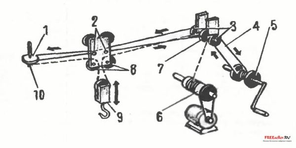
Rice. 1. Diagram of a crane that you can make yourself:
1 - block, 2 - crane boom, 3 - crane trolley, 4 - telescopic stand, 5 - paired angles, 6 - boom base blocks, 7 - I-beam, 8 - struts, 9 - crane trolley moving winch, 10 - load frame , 11 - lifting mechanism winch, 12 - electric winch drive, 13 - stand corner, 14,15 - M 16 bolts, 16 - lifting hook assembled with a block.
The crane consists of a horizontal boom beam (the crane trolley moves along it) and vertical support posts made of steel pipes, to which horizontal beams are attached. The crane is collapsible, which allows you to move it from place to place.
Construction of crane stands.
They are made of pipes with a diameter of 140 mm. Their height can be increased up to 3 m using telescopic incoming pipes. To prevent the posts from sinking into the ground, corners are welded to the base. Welded to the top of the supports horizontal beam- two corners joined together x 65 x 10 mm. A horizontal guide is attached to it from below with four bolts - an I-beam No. 20, having dimensions of 200 x 100 x 5.2 mm, 3000 mm long, along which the crane trolley moves.
The second pair of supports for the guide consists of two vertical pipes, connected at the top and bottom. For greater stability, two inclined supports are welded to them, which in turn connect the racks with a rectangular frame. The latter prevents the crane from tipping over, as it serves as a base for laying sandbags or concrete blocks.
An important feature of a jib crane is its control. Those who will build and operate it need to know: the crane has a lifting and moving device. If necessary, any part can be lowered below the zero mark (into a pit or trench). The entire system of cables and pulleys of the lifting device is driven by an electric motor. The trolley is moved by a hand winch using a cable. One end of it is fixed to the trolley, then the cable goes through the block to the drum, makes five turns and, again passed through the blocks at the base and at the end of the boom, is fixed to the crane trolley.
The hook is lifted by a cable, fixed at one end to the winch and passing successively through the blocks of the base, boom and crane trolley; then the cable goes down, forms a loop on which a block with a hook is suspended, and is secured to the end of the boom through the block of the crane trolley.
Rice. 2. Diagram of the mechanism for lifting and moving the load:
1 - boom end block, 2 - cable fastening pin on the crane trolley, 3 - boom base blocks of the crane trolley moving mechanism, 4 - cable moving the crane trolley, 5 - drum, 6 - hoisting mechanism winch, 7 - hoisting mechanism boom base block , 8 - blocks of the maroon trolley, 9 - block of the hook, 10 - assembly for securing the lifting cable.
The lifting device can also be driven by a conventional manual winch, which will provide the crane with complete autonomy.
Before starting work, you should carefully check the strength of the nodes and supports. Standing under the boom is not allowed - this is the basic safety rule at any construction site.
We hope that there will be farmers and gardeners who will build a crane to make their work easier. Maybe not like that. But similar. The main thing is that he helps in the work.


